
|
|
[China]

Trade Verify
Address: 4/F, Block C, HeHengXing Science & Technology Park, 19 MinQing Road, LongHua District, Shenzhen City, GuangDong Province, China
Contact name:Sun

Shenzhen Socay Electronics Co., Ltd. |
|
Verified Suppliers
|
|
|
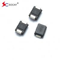
(TSS) P0080SB DO-214AA (SMB) Package Thyristor Surge Suppressors VDRM 6V VS 25V Marking P008B
DATASHEET: PXXX0SB_v2103.1.pdf
| Part Number | Marking | VDRM @IDRM=5μA | VS ① @100V/μS | VT @IT=2.2A | IS | IT | IH | C0 ② @1MHz, 2V bias |
| V min | V max | V max | mA max | A max | mA min | pF typ | ||
| P0080SB | P008B | 6 | 25 | 4 | 800 | 2.2 | 50 | 80 |
| P0300SB | P03B | 25 | 40 | 4 | 800 | 2.2 | 50 | 80 |
| P0640SB | P06B | 58 | 77 | 4 | 800 | 2.2 | 150 | 80 |
| P0720SB | P07B | 65 | 88 | 4 | 800 | 2.2 | 150 | 75 |
| P0900SB | P09B | 75 | 98 | 4 | 800 | 2.2 | 150 | 70 |
| P1100SB | P11B | 90 | 130 | 4 | 800 | 2.2 | 150 | 70 |
| P1300SB | P13B | 120 | 160 | 4 | 800 | 2.2 | 150 | 65 |
| P1500SB | P15B | 140 | 180 | 4 | 800 | 2.2 | 150 | 65 |
| P1800SB | P18B | 170 | 220 | 4 | 800 | 2.2 | 150 | 65 |
| P2300SB | P23B | 190 | 260 | 4 | 800 | 2.2 | 150 | 60 |
| P2600SB | P26B | 220 | 300 | 4 | 800 | 2.2 | 150 | 60 |
| P3100SB | P31B | 275 | 350 | 4 | 800 | 2.2 | 150 | 50 |
| P3500SB | P35B | 320 | 400 | 4 | 800 | 2.2 | 150 | 50 |
| P4200SB | P42B | 400 | 520 | 4 | 800 | 2.2 | 150 | 40 |
Notes: ① Vs is measured at 100KV/s. ② Off-state capacitance is measured in VDC=2V, VRMS=1V, f=1MHz. | ||||||||
About TSS
The TSS are characterised by precise conduction, fast response, high surge absorption capacity, biaxial symmetry and high reliability.

Description:
PXXX0SB Series are designed to protect broadband equipment such as modems, line card, CPE and DSL from damaging over-voltage transients.The series provides a surface mount solution that enables equipment to comply with global regulatory standards.
Features:
u Low voltage overshoot u Low on-state voltage u Does not degrade surge capability after multiple surge events within limit u Fails short circuit when surged in excess of ratings u Low Capacitance |
| Parameter | Definition |
| IS | Switching Current - maximum current required to switch to on state |
| IDRM | Leakage Current - maximum peak off-state current measured at VDRM |
| IH | Holding Current - minimum current required to maintain on state |
| IT | On-state Current - maximum rated continuous on-state current |
| VS | Switching Voltage - maximum voltage prior to switching to on stat |
| VDRM | Peak Off-state Voltage - maximum voltage that can be applied while maintaining off state |
| VT | On-state Voltage - maximum voltage measured at rated on-state current |
| C0 | Off-state Capacitance - typical capacitance measured in off state |
| Series | 2/10μS1 | 8/20μS1 | 10/160μS1 | 10/560μS1 | 10/1000μS1 | 5/310μS1 | ITSM 50/60 Hz | di/dt | |
| 2/10μS2 | 1.2/50μS2 | 10/160μS2 | 10/560μS2 | 10/1000μS2 | 10/700μS2 | ||||
| A min | A min | A min | A min | A min | A min | A min | Amps/µs max | ||
| B | 250 | 250 | 150 | 100 | 80 | 100 | 30 | 500 | |
Notes:
|
- Peak pulse current rating (IPP) is repetitive and guaranteed for the life of the product. - IPP ratings applicable over temperature range of -40ºC to +85ºC - The device must initially be in thermal equilibrium with -40°C < TJ < +150°C
| ||||||||
| High Temp Voltage Blocking | 80% Rated VDRM (VAC Peak ) +125°C or +150°C, Lead Material Copper Alloy High Temp Voltage Blocking 504 or 1008 hrs. MIL-STD-750 (Method 1040) JEDEC, JESD22-A-101 | |
| Temp Cycling | -65°C to +150°C, 15 min. dwell, 10 up to 100 cycles. MIL-STD-750 (Method 1051) EIA/JEDEC, JESD22-A104 | |
| Biased Temp & Humidity | 52 VDC (+85°C) 85%RH, 504 up to 1008 hrs. EIA/ JEDEC, JESD22-A-101 | |
| High Temp Storage | +150°C 1008 hrs. MIL-STD-750 (Method 1031) JEDEC, JESD22-A-101 | |
| Low Temp Storage | -65°C, 1008 hrs. | |
| Thermal Shock | 0°C to +100°C, 5 min. dwell, 10 sec. transfer, Thermal Shock 10 cycles. MIL-STD-750 (Method 1056) JEDEC, JESD22-A-106 | |
| Autoclave (Pressure Cooker Test) | +121°C, 100%RH, 2atm, 24 up to 168 hrs. EIA/Cooker Test) JEDEC, JESD22-A-102 | |
| Resistance to Solder Heat | +260°C, 30 secs. MIL-STD-750 (Method 2031 | |
| Moisture Sensitivity Level | 85%RH, +85°C, 168 hrs., 3 reflow cycles Level (+260°C Peak). JEDEC-J-STD-020, Level 1 |
| Lead Material | Copper Alloy | |
| Terminal Finish | 100% Matte-Tin Plated | |
| Body Material | UL recognized epoxy meeting flammability classification 94V-0 |
| Part Number | Component Package | Quantity | Packaging Option | Packaging Specification | |
| Pxxx0SB | DO-214AA | 2500 | Tape & Reel -12mm/13″tape | EIA -481 - D |


Selection of semiconductor discharge tubes:
When selecting TSS, the following principles should generally be followed:
1. Selection of cut-off voltage VDRM: The cut-off voltage must be greater than the maximum operating voltage of the protected circuit;
2. Selection of transition voltage VBO: The transition voltage must be less than the maximum transient peak voltage that the equipment can withstand;
3. Selection of the holding current IH: the holding current must be greater than the operating current and short-circuit current of the equipment;
4. Selection of parasitic capacitance C: The parasitic capacitance is selected according to the insertion loss allowed by the circuit or the frequency of signal transmission;
5. Selection of surge current: Different levels of surge current are selected according to the requirements of the circuit or surge test standards.


