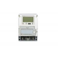
Smart Meter in Automatic Meter Reading System Single Phase Two
Wires DLMS/COSEM
Summary:
DDZY150 single phase local fee control smart meter is a intelligent
electricity metering product, which suit for measuring 220V/50Hz
single phase active AC power. It has independent optical and RS485
interface, and also with standard interface of carrier
communication module, which can work with carrier communication
module from different suppliers. It can support for fee control
function. With advantages of high reliable, high accuracy, long
life, wide range and etc, it can widely used in city, country and
enterprises where need to measure single phase AC power.
Standard: IEC 62053-21 Electricity metering equipment (a.c.)
–Particular requirements –
Working Principle:
Measured AC voltage and current have been sampled and transported
to professional metering chip, after digital processing, they have
been changed to the pulse signal, which in direct proportion to
active power, and then sent to microprocessor. Microprocessor would
accumulate the pulse signal according to the tariff, then get total
power and tariff power and put them in register. At the same time,
the microprocessor finishes the function of display and changeover
with external messages. Please take attention to the Figure 1
Features:
1) Metering:
- Measuring for positive and reverse active power, storage the data,
and according to which setting active group
- Multi tariff. For active power, it can accumulate and storage
total, top, peak, flat, valley power according to certain period.
- It can storage total power and power for each tariff for last 12
months. The boundary is 24:00pm of end of month, or on the hour
from 1st to 28th for every month.
2) Remote Fee Control:
It finished parameter setting and remote purchasing through RS485,
carrier and other virtual medium..
3) Measuring and Monitoring
It can measure and monitor operating parameter such as voltage,
current (including zero line current), power, power factor and etc.
The error would not exceed ±1
4) Event Log
5) Display:
- The following information would be displayed in meter:
- The unit for power is kWh, and 8 digital display
- LCD backlight wake up methods including switch wake up, infrared
wake up(any infrared can work) and etc. In normal use, the life
time for LCD won’t be less than 10 years
- When power off, the backlight can be woke up by switch; If no
operation after waking up, LCD would close automatically after a
cycle; If operation exist, LCD would close automatically in 30
seconds after operation.
- Indicator: --Pulse Red, it is off in normal condition, and would be
flash when measuring active power
- Alarm Red, it is off in normal condition, and would be on when
alarming
- Trip Yellow, it is off in normal condition, and would be on when
load switch disconnect
6) Alarm:
When the following faults or alarm appear, LCD would stop on the
certain code and backlight keep on.
- Error Code
- Err-01 Control Loop Error
- Err-04 Low Voltage for Clock Battery
- Err-08 Clock Error
- Err-10 Error for Certification
- Err-16 Error for Key Correction
7) Freezing:
- Time Freezing: Freezing meter data according to the promissory time
and interval; It can keep at least 12 times for each frozen
fraction.
- Instantaneous Freezing: Under improper condition, freezing current
date time, all power and important measurement data; It keeps the
data for last 3 times.
- Appoint Freezing: In any case of older/new tariff, step tariff
changeover and other situation which is necessary, the meter would
freeze power and other important data on the changeover time, It
keeps the data for last 2 times
- Day Freezing: Store power on 0.00am for each day, total for 2 month
- On Hour Freezing: Store active power for hour or half an hour,
total for 96 data
8) Timing:
- Build in clock circuit with temperature compensation function, the
calendar, timing, leap year can be changed over automatically. The
output frequency for inner clock terminal is 1Hz. Between -25℃ to
+60℃, clock accuracy is no more than ±1 s/d; Under reference
temperature 23℃, clock accuracy is no more than ±0.5 s/d.
- The accepted time broadcasting is no more than 5 min. No need to
match with programming switch and communication password when time
broadcasting. It can be set according to the inquire, and it avoid
from handling in 5 min at the time when freezing or data storing.
9) Pulse Output:
Meter has function for LED pulse and electrical pulse output which
comes direct ratio with measuring energy. Optical test output
device should comply gb/t17215.211-2006, electricity test output
device should comply GB/T15284-2002. It has signal output terminal
for clock, and the output frequency is 1Hz
10) Load Switch:
External load switch, there is a group of switch signal for meter
output. Volume of switch point is AC 220V/2A. Under normal
condition, switch signal for output should keep switch on of load
switch, allow for power on; When reach certain condition, switch
signal for output should drive operation for external load switch,
power off.
Main Parameters:
Consumption: Voltage Circuit Consumption(Out of Communication Status) ≤1.5W,
10VA
Voltage Circuit Consumption(Under Communication Status) ≤3.0W, 12VA
Current Circuit Consumption ≤1VA(Ib)
Working Temperature: -25℃~60℃
Maximum Working Temperature: : -40℃~70℃
Maximum Storage and Transportation Temperature: -40℃~70℃
Relative Humidity: Annual Average<75%
Clock Accuracy: ≤0.5S/D (Reference Temperature 23℃)
Capacity of Li-Ion Battery: ≥1.2Ah, the working time since power off≥ 5 years.
Data Storage Period ≥ 10 years
Life Time ≥ 10 years
Dimension: 112*160*71 mm
Weight: 0.8kg
Communication Rate for Optical: 1200bps
Communication Rate for RS485: 2400bps (Typical Value)
600bps, 1200bps, 2400bps, 4800bps, 9600bps (Can be set)
Installation:
- Size for installing, see attached Figure 3. There is hanging hole
for screw on the top of meter, using M4 screw for fixing. Also 2
installing holes on the bottom of meter, which using M4*10/M4*12
screws for fixing to wiring board.
- Connection for main terminal and auxiliary terminals.
- See Figure 4 for connection of main terminal, 1 for L input, 2 for
L output, 3 for N input, 4 for N output
- There are 8 auxiliary terminals above of main terminal, 5.6 for
trip control, 7.8 for pulse output, 9.10 for multi function output,
11.12 for RS485
Notes:
- No device inside can be adjust by user.
- When installing and using, there should be tight enough for each
connection line, to avoid from any bad connection which would cause
heating to damage the meter. Make sure of the right connection of
input and output. Please install the meter on local where is dry
and ventilated. Don’t put in the place under direct highlight,
especial for infrared window. When using infrared communication, it
should take more attention to avoid from any disturb from highlight
to infrared interface, and please adjust the distance and angel of
infrared, to make sure of reliable communication.