
|
|
[China]

Trade Verify
Address: Room 101, 1st Floor, No. 6, Third Street, Pingshan Industrial Zone 511495, Shibi Street, Panyu District, Guangzhou, China
Contact name:Zoe Zou

Sinuo Testing Equipment Co. , Limited |
|
Verified Suppliers
|
|
|
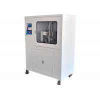
IEC62196 Electric Vehicle Charging Plug And Socket Misalignment Tester
Product Information:
This misalignment test apparatus conforms to IEC62196-3 clause 36.3, figure 18.
Technical Parameters:
| Power | AC220V, 60Hz |
| Control Method | PLC control, touch screen operation |
| Station | One |
| Drive Mode | servo motor, two pcs, X and Y |
| Force | 0-500N |
| Force holding time | 0-999.9s |
| Interval time | 0-999.9s |
| Force application direction | -X, +X, -Y, +Y |
| Specimen mounting bracket | 30 ° slope, 1000mm height from the ground |
| Overall dimensions of equipment | 100mm×400mm×1500mm,150kg |
During temperature rise test, immediately following temperature stabilization, the accessories are subjected to external mechanical loads as illustrated in Figure 18.

Using a force gauge, apply a load of 100 N with a tolerance of -0/+10 N as illustrated in Figure 19 in each direction. The load should be applied for a minimum of 1 min. Following this load application, the load should be removed for a time of 10 s and the load re-applied in the next direction within 10 s. This process is continued until the load is applied in the 4 directions (-X, +X, -Y, +Y) as illustrated in Figure 19.
The equipment adopts X, Y (Figure 19) sliding table, driven by servo motor and monitored by force value sensor. When the force value reaches the required time for automatic constant force holding, it will automatically switch to another direction for test.

Operation Instructions:
1 Rotate the handwheel to move the action mechanism to the right and expose the mounting interface of the socket mounting base plate.
2 Choose corresponding socket mounting base plate according to sample socket, then fixed the socket mounting base plate to the mounting interface. And the wire of the sample is extracted from the hole below the mounting interface.
3 Rotate the handwheel to move the action mechanism to the left, then open the board of the sensor closest to the door, loosen the nut to open the retainer block, the board will be fixed automatically after rotating 90° upward. Then loosen the positioning screws on the sensors mounting boards, move the left and right sensors outward, and move the upper and lower sensors upward and downward, make the sensors and away from the center, in order to not affect the installation of the plug.
4 Insert the plug into the socket, pull out the position locating pin, and put down the plate, buckle the retainer block on the screw, lock the nut, and put down the wire of the plug from the opening hole on the right side.
5 Press Manual on the touch screen, the then press Left-Right-Up-Down to adjust X-axis sensors and the tail of charging gun to be on the same center line. And adjust the heads of the four sensors around 30mm away from charging gun, then locking screws to secure the sensors.
6 Close the observation window after the sample installed, then open the door below, and lead the wires of plug, socket and thermocouple from the small opening on the back of the apparatus, connected to the external temperature rise test machine (the external temperature rise test machine is prepared by client).
7 Press Reset in control screen, please assure that the display value of four sensors has been cleared to zero and confirmed the initial position.
8 Press Parameter into the parameter screen, set all the parameters
9 Return to the control interface, wait for the temperature rise to be stabilized and press start to start the test. The test operation steps are as follows: -X force applied →force reached and hold 60s→ force released 10s→+X apply applied →force reached and hold 60s→ force released 10s→-Y force applied → force reached and hold 60s→ force released 10s→+Y force applied → force reached and hold 60s→ force released. During operation, the force value will be displayed in real time and there are corresponding curves in four directions


