

Active Member
|
[China]

Address: No. 301A, 3F, C6 Bldg, Hengfeng,No 739 Zhoushi Rd,Hezhou, Hangcheng, Bao'an, Shenzhen City, 518000 China
Contact name:Spring_zhang

Ain Technology (Shenzhen) Co., Ltd |
|
|
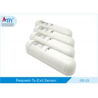
REQUEST-TO-EXIT Passive Infrared Sensor
| Supply Voltage | 12-24VDC or VAC . | ||||
| Supply Current | 18-30mA@12-24VDC,45-80mA@12-24VAC | ||||
| Relay Output | 2C Contact(N.C/N.O) , 24VDC 1A Max. | ||||
| Detection Type | Passive infrared | ||||
| Relay Hold Time | 0.5-64 seconds | ||||
| LED Indication | Red | ||||
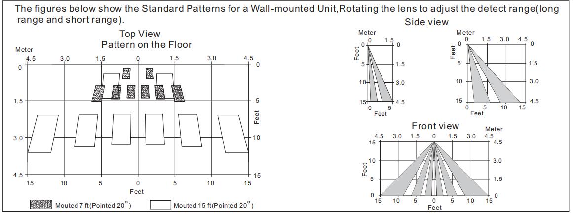
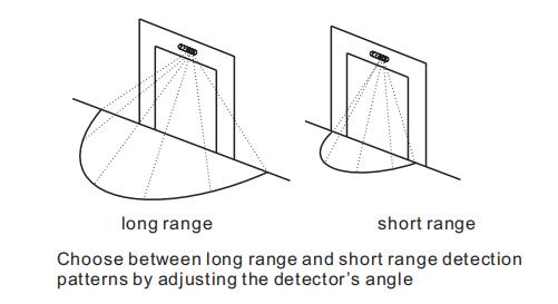
| Range | Coverage 12x5 ft at 7ft high,30x12 ft at 15 ft high(Adjustment ) | ||||
| Operating Temperature | - 14°F to 131°F(- 10° C to 55°C) | ||||
| Weight | 0. 4lb( 0. 18kg) | ||||
| Humidity | 0-95% non-condensing | ||||
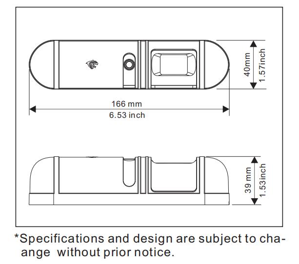
| Dimensions | 6.53"Wx1. 57"Hx1. 53"D( 166x40x39mm) |

| Table1: Latch Time DIP Switch Settings | ||||||
| Time(sec) | Switch 1 | Switch 2 | Switch 3 | |||
| 0.5(Default) | OFF | OFF | OFF | |||
| 1 | ON | OFF | OFF | |||
| 2 | OFF | ON | OFF | |||
| 4 | ON | ON | OFF | |||
| 8 | OFF | OFF | ON | |||
| 16 | ON | OFF | ON | |||
| 32 | OFF | ON | ON | |||
| 64 | ON | ON | ON | |||
| Table 2: LED Enable/Disable DIP Switch Settings | |||||
| Switch 4 | Function | ||||
| OFF | Disabled | ||||
| ON | Enabled (Default) | ||||
| Table 3:Relay Mode DIP Switch Settings | |||||
| Switch 5 | Function | ||||
| OFF | Fail Secure | ||||
| ON | Fail safe(Default) | ||||
| Table 4:Resettable/Non-resettable DIP Swithc Settings | |||||
| Switch 6 | Function | ||||
| OFF | Non-resettable | ||||
| ON | Resettable (Default) | ||||
| TROUBLE | TROUBLE CAUSE | REMEDY | |||||||
| Unit does not power up | No or low imput power. | Apply proper input voltage. | |||||||
| Input power polarity reversed. | Correct wiring polarity. | ||||||||
| Alarm LED does not light | LED jumper is set to “LED OFF”. | Set LED jumper to “LED ENABLE” | |||||||
| Incorrect sensor mounting height | Increase / decrease mounting height | ||||||||
| LED indicates light,no signal output | Incorrect wiring at output terminals | Correct wiring fault. | |||||||
| Lightning damage | Replace sensor. | ||||||||
| Unit continues to operate after the input power has been disconnected. | The wire to the “V-” power input was discon- nected, the “V+” is still connected. | Disconnect wire from the “V+” power input. | |||||||
MAINTENANCE


