
|
|
[China]

Trade Verify
Address: 6-11C Shidai Jingyuan,Fuyong, Baoan, Shenzhen, Guangdong, China 518103
Contact name:Ivy Deng

Bicheng Electronics Technology Co., Ltd |
|
Verified Suppliers
|
|
|

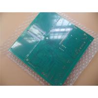
| Number of Layers | 8 |
| Board Type | Multilayer PCB |
| Board size | 210.72 x 212.42mm=1UP |
| Board Thickness | 1.60 mm +/-0.16 |
| Board Material | FR-4 |
| Board Material Supplier | ITEQ |
| Tg Value of Board Material | 170℃ |
| PTH Cu thickness | ≥20 um |
| Inner Iayer Cu thicknes | 35 um (1oz) |
| Surface Cu thickness | 35 um (1oz) |
| Solder Mask Type and Model No. | LPSM, PSR-2000GT600D |
| Solder Mask Supplier | TAIYO |
| Solder Mask Colour | Green |
| Number of Solder Masks | 2 |
| Thickness of Solder Mask | 14 um |
| Type of Silkscreen Ink | IJR-4000 MW300 |
| Supplier of Silkscreen | TAIYO |
| Color of Silkscreen | White |
| Number of Silkscreen | 1 |
| Mininum Trace (mil) | 5.8 mil |
| Minimum Gap(mil) | 5.4 mil |
| Surface Finish | Immersion Gold |
| RoHS Required | Yes |
| Warpage | 0.25% |
| Thermal Shock Test | Pass, 288±5℃,10 seconds, 3 cycles. No delamination, no blistering. |
| Solderablity Test | Pass, 255±5℃,5 seconds Wetting Area Least 95% |
| Function | 100% Pass electrical test |
| Workmanship | Compliance with IPC-A-600H & IPC-6012C Class 2 |
| Drill table (mm) | |
| T1 | 0.450 |
| T2 | 0.600 |
| T3 | 0.800 |
| T4 | 0.900 |
| T5 | 0.950 |
| T6 | 1.000 |
| T7 | 1.250 |
| T8 | 1.300 |
| T9 | 1.400 |
| T10 | 1.600 |
| T11 | 1.700 |
| T12 | 2.000 |
| T13 | 2.550 |
| T14 | 3.000 |
| T15 | 3.250 |
| T16 | 3.500 |
| Serial NO. | Procedure | Item | Manufacturing capability | ||
| Large volume (S<100 m²) | Middle volume (S<10 m²) | Prototype(S<1m²) | |||
| 66 | Contour process | Method of contour process | CNC milling, V-CUT, Break-out tap, break-out holes, Punching | ||
| 67 | Minimum router | 0.8mm | |||
| 68 | Min.tolerance of contour | ±0.15mm | ±0.13mm | ±0.1mm | |
| 69 | Min.distance of milling contour(no copper exposure) | 12mil | 10mil | 8mil | |
| 70 | Angle of V-CUT | 20,30,45,60 ±5 degree | |||
| 71 | Degree of symmetry of V-CUT | ±6mil | ±5mil | ±4mil | |
| 72 | Tolerance of residual thickness of V-CUT | ±6mil | ±5mil | ±4mil | |
| 73 | Tolerance of Chamfer angle of Gold finger | ±5 degree | ±5 degree | ±5 degree | |
| 74 | Tolerance of residual thickness of bevel edge of gold finger | ±5mil | ±5mil | ±5mil | |
| 75 | Min radius of inner corner | 0.4mm | |||
| 76 | Min. distance from edge to V-Cut (no copper exposure) | 18mil (1.6mm Thick, 20 degree V-groove cutter) | 14mil(1.6mm Thick, 20 degree V-groove cutter) | 12mil (1.6mm Thick, 20 degree V-groove cutter) | |
| 77 | 20mil (1.6mm Thick, 30 degree V-groove cutter) | 18mil (1.6mm Thick, 30 degree V-groove cutter) | 16mil (1.6mm Thick, 30 degree V-groove cutter) | ||
| 78 | 24mil (1.6mm Thick, 45 degree V-groove cutter) | 22mil (1.6mm Thick, 45 degree V-groove cutter) | 20mil (1.6mm Thick, 45 degree V-groove cutter) | ||
| 79 | 30mil (1.6mm Thick, 60 degree V-groove cutter) | 28mil (1.6mm Thick, 60 degree V-groove cutter) | 26mil (1.6mm Thick, 60 degree V-groove cutter) | ||


