|
|
[China]

Trade Verify
Address: Shenzhen YingSheng Technology Co., Ltd 805, Tongxin Technology Building, Qiaotou Community, Fuhai Street, Baoan District, Shenzhen
Contact name:Zhou

Shenzhen Yingsheng Technology Co., Ltd. |
|
Verified Suppliers
|
|
|
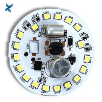
Led Pcb Board DC12V Metal Core Print Circuit Boards for High-power Scanners
Some Considerations for Designing an LED PCB
Designing an LED PCB is a process that requires some standards and rules to be followed.
Here is what it takes to design an LED PCB:
Component Placement: the right component placement is what it takes to design an efficient LED circuit board.
Placing the right component at the right spot is crucial in PCB designing.
Along with LEDs, an LED PCB contains other components such as connectors, resistors, and thermistors, which need to be placed at a suitable distance from each other.
The creepage (the shortest distance between two components) and the clearance (distance measured through the air) should be considered when designing an LED PCB to avoid damaging consequences such as overvoltage.
PCB Material: choosing the right material for your LED PCB is challenging because there are multiple materials available in the market, and each has its own pros and cons.
You’ll need to study their merits and demerits to find out which material is suitable for your application.
You might need professional help for it, and the best place to go to is YScircuit.
We provide free and professional suggestions.
Thermal Management: LEDs and other components placed on the PCB will certainly dissipate heat energy, and if that energy is not channeled the right way, then it might end up damaging your circuit board.
The addition of vias and heat sinks will allow you to manage the heat energy present within the board.
Professionals at PCBONLINE knows exactly what it takes to manage the heat produced by electronic components.
Tracking: tracking is the process of ensuring that no part of the net is
left open or is forming a short circuit.
After the components are placed, the process of tracking begins.
The flow of current is also monitored such that it does not contribute to the production of heat energy in the circuit.
| Layer | 1-24 |
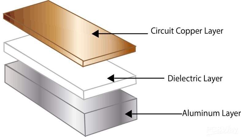
| Material | Aluminum core (Domestic 1060), Copper core, FR4 covering |
| Thickness (Finished Board) | 0.8 mm-5.0 mm |
| Max. Board Size | 610 mm*610 mm |
| Copper weight (finished) | 0.5 oz-4.0 oz |
| Surface Finish | Hot air solder leveling (HASL) Lead-free HASL: RoHS compliant Electroless nickel/immersion gold (ENIG): RoHS compliant |
| Min. Tracing/Spacing | 4 mil/4 mil |
| Min. diameter of drill | 8mil |
| Min. Annular ring | 4mil |
| Soldermask Color | Green, red, black, yellow, white, blue, green matt, black matt |
| Silkscreen Legend Color | White, Black, Yellow |
| Countersink holes | Yes |
| Screw holes | Yes |
| layer/m² | S<1㎡ | S<3㎡ | S<6㎡ | S<10㎡ | S<13㎡ | S<16㎡ | S<20㎡ | S<30㎡ | S<40㎡ | S<50㎡ | S<65㎡ | S<85㎡ | S<100㎡ |
| 1L | 4wds | 6wds | 7wds | 7wds | 9wds | 9wds | 10wds | 10wds | 10wds | 12wds | 14wds | 15wds | 16wds |
| 2L | 4wds | 6wds | 9wds | 9wds | 11wds | 12wds | 13wds | 13wds | 15wds | 15wds | 15wds | 15wds | 18wds |
| 4L | 6wds | 8wds | 12wds | 12wds | 14wds | 14wds | 14wds | 14wds | 15wds | 20wds | 25wds | 25wds | 28wds |
| 6L | 7wds | 9wds | 13wds | 13wds | 17wds | 18wds | 20wds | 22wds | 24wds | 25wds | 26wds | 28wds | 30wds |
| 8L | 9wds | 12wds | 15wds | 18wds | 20wds | 20wds | 22wds | 24wds | 26wds | 27wds | 28wds | 30wds | 30wds |
| 10L | 10wds | 13wds | 17wds | 18wds | 20wds | 20wds | 22wds | 24wds | 26wds | 27wds | 28wds | 30wds | 30wds |
| 12L | 10wds | 15wds | 17wds | 18wds | 20wds | 20wds | 22wds | 24wds | 26wds | 27wds | 28wds | 30wds | 30wds |
| 14L | 10wds | 16wds | 17wds | 18wds | 20wds | 20wds | 22wds | 24wds | 26wds | 27wds | 28wds | 30wds | 30wds |
| 16L | 10wds | 16wds | 17wds | 18wds | 20wds | 20wds | 22wds | 24wds | 26wds | 27wds | 28wds | 30wds | 30wds |


FQA
1. The advantages of LED PCB
With the electronic products is more and more smaller and thinner,
making it popular to use LED PCB, and there are various advantages
with using LED PCB as follows:
There are two main reasons which make the LED PCB be popular in addition to increasing the light output of the fixture with integrating multiple LED components.
2. SMD LEDs in your PCB
There are many devices including LEDs on a PCB using surface
mounted components.
If the wires are quite thin, through hole components can bend
slightly so that it looks cheap from the outside.
If making it right to solder the SMD LED, it will be rigid on the
board. What’s more, it can also place the SMD LED behind a screen,
and cheaper LED that use a bulb will stick out through the
packaging.
So it can place the SMD LED behind a small screen in your packaging
to be cleaner for your device.
As you know, many PCBs that contain LEDs are fabricated with
multilayer FR-4 substrates, so you need to have a pattern of
closely-spaced filled or plated through vias under each component
so that it can transmit heat, as well as get to your power and
ground layers.
If your LEDs have a small footprint and are surfaced mounted, it
can use our vias.
Probably there will be a weak solder joint or even tombstoning
because it doesn’t fill or plate over the vias and then solder can
wick into the vias during assembly, so the reason why it’s better
to just use SMD LEDs on an LED lighting array is that the problem
with wicking.
A single LED with decent power output will not lead to damaging to
your board because of undue thermal.
However, if you are going to have a system for lighting
applications, it will need to suffer from a massive heat for the
board that supports your LEDs, and make it hard to cool with
traditional methods for the boards.
Because the individual LEDs are too small, you can’t really attach
a heatsink anywhere, and a heatsink will block the emitted light
anyways.
Because there is a great demand on thermal, the boards with a metal
core are usually used in LED lighting applications due to their
ability to dissipate a great deal of heat.
In general, aluminum is used for LED lighting applications as the
metal core in PCB.
What’s more, aluminum is the most metal used as the core among all
the possible metal core PCBs.
As well as copper and iron are used for metal core PCBs.