
|
|
[China]

Trade Verify
Address: No.2-A-609, NO.1 Longyu Road, Jianxi District, Luoyang, Henan, China
Contact name:David

Luoyang Zhongtai Industrial Co., Ltd. |
|
Verified Suppliers
|
|
|
ZZJ Type Intelligent Brake Detection Device With Mining Machine Spare Parts
1. Product description of ZZJ type intelligent brake detection device with mining machine spare parts
ZZJ type intelligent brake detection device is used to detect the upper disc brake of hoist brake, which can detect the wear degree of brake skin and fatigue degree of spring, and display it directly in the form of numbers. When the brake wear and spring fatigue exceed the set alarm value, output a switch signal to inform the upper electronic control system, and detect the digital flashing on the module to indicate the module alarm. The detection module is intelligent, which can upload the digital quantity and alarm state to the upper computer by means of communication (the corresponding hardware and software should be added).
2. Product parameters of ZZJ type intelligent brake detection device with mining machine spare parts
(1) System composition: each pair of gates consists of a detection module and two sensors to form a detection unit; Each brake base is installed with a control box, according to the brake base installed on the logarithm, the control box loaded with the corresponding number of detection modules; The control boxes are connected in parallel through cables, and a power supply module provides the working power.
(2) Installation: the control box is installed on the brake base; The sensor is installed in the rear of the brake seat, so that the sensor detection shaft is always on the top of the brake seat; The sensor is connected to the corresponding detection module.
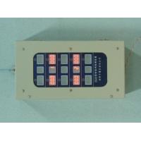
(3) Connection methods: each control on test module on the bottom of the box has a 6 line terminals, terminal are defined as shown in figure: left 12 v | | 0 v | | D1 and D2 | D | -- - | D right; Including 12 v | | | 0 v to provide the 12 v power supply; | | | D2 D1 is a pair of dry contact, is used to output alarm signal; | D | -- - | D is communication terminals. The 6-wire terminals in several control boxes are connected together. Each detection module has a 3-wire wiring terminal on the left and right sides for connecting signal cables to the left and right sensors. Terminal and sensor connection as shown in figure: | | left palm black | | right.
(4) Detection parameters:
maximum distance: 25mm
Detection error: 0.1mm
(5) Dial setting: each detection and to the right of the module has an 8-bit dial, is used to set the detection module parameters, as shown in figure: left | | S1 S2 | S3 | S4 | S5 | S6 | S7 | S8 | right.
As follows:
The ON value is 1 when the dial is up, and the ON value is 0 when the dial is down |
|
S1, S2, S3, and S4 form a four-digit binary address |
|
S5 is the brake skin wear alarm value setting | 0 is 1.5mm, 1 is 2.0mm |
S6 is spring fatigue alarm setting | 0 is 0.5mm, 1 is 1.0mm |
S7 is the choice of brake skin wear alarm mode
| 0 is the alarm when one side reaches the alarm value |
1 is the alarm when the sum of both sides reaches 2 times of the alarm value | |
S8 is the last module setting | The last module is set to 1 and the rest to 0 |
(6) Debugging method: After installation, for the first time in opened state, adjust the sensor position, before and after the detection module is shown in the near 20.0, continue to press the reset button for about 2 seconds on the test module, test module display on 0.0, here is zero, after testing it to zero, as negative said the size of the brake shoe clearance, positive number indicates the degree of spring fatigue, When the set value of alarm is reached, the alarm will be reported. After each switch adjustment, the reset key must be pressed to clear. Under the condition that the sensor's detection axis is fully released, press the reset button on the detection module continuously for about 2 seconds, and the display will be 00.0. Then press the sensor's detection axis, and the display will be 00.0 -- 24.9. This display is used for the installation of the new brake skin.
(7) The alarm output mode is A pair of dry contacts with A capacity of 0.5A, which are closed with alarm and disconnected without alarm.


