
|
|
[China]

Trade Verify
Address: Guangzhou Sunrise Int'l Co., Ltd Room 819, Gateway 5, Xinguangcong Motor Parts City, 113 North Baiyun Avenue, Baiyun District, Guangzhou City, Guangdong Province, China
Contact name:Sunny

Guangzhou Sunrise Int'l Co., Ltd |
|
Verified Suppliers
|
|
|
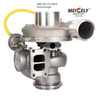
Turbocharger 1885156 Compatible with Caterpillar Track Loaders 6 C-9 C-15 973C D6R II
Specification:
| Specification As Follows | |
| OE Number | 188 5156(315-9810) |
| Material | Steel |
| Engine Model | D6R II |
| Fuel | Diesel |
| Capacity | N/A |
| Weight | 14kgs |
| Compressor wheel Material | N/A |
| Displacement | N/A |
| ASIN | B0CWXZJBKQ |
| Certificate | ISO9001 |
| Warranty | 6 Months |
Description:
Interchanges OEM Caterpillar Number 1885156
We have a wide range of air system components in stock for your
machine. All our air system components are made with premium OEM
grade materials to ensure exact fitment and longevity. We offer
turbochargers, compressors, receiver driers, blowers, manifolds,
and more.
Alignment
Checking The Face Of Engine Flywheel Housing.
(1) Engine. (2) Dial indicator. (3) Crankshaft. (4) Flywheel. (5)
Flywheel housing.1. Bolt a thousandths increment dial indicator or
gauge to the engine flywheel so that the indicator is perpendicular
to the face of the engine flywheel housing, and the indicator stem
is riding on the face of the flange. 2. Rotate the engine flywheel,
always keeping a thrust in the same direction, and note the face
deviation of the engine flywheel housing flange. The face deviation
must not exceed the figures given in the above chart.
Checking The Bore Of Engine Flywheel Housing.
(1) Engine. (2) Dial indicator. (3) Crankshaft. (4) Flywheel. (5)
Flywheel housing.3. With the indicator mounted, position the
indicator stem so that it will ride on the bore of the engine
flywheel housing.4. Rotate the engine flywheel and note the bore
eccentricity of the engine flywheel housing bore. See Chart.
Checking The Driving Ring Surface Of Engine Flywheel.
(1) Engine. (2) Dial indicator. (3) Crankshaft. (4) Flywheel. (5)
Flywheel housing.5. Bolt a thousandths dial indicator or gauge to
the engine flywheel housing so that the indicator is perpendicular
to the engine flywheel, and the indicator stem is riding on the
face of the flywheel.Rotate the flywheel. The variation of the face
runout of the surface to which the driving gear is bolted should
not exceed 0.012 mm (.0005 in) per inch of diameter.
Checking The Driving Ring Pilot Bore of Engine Flywheel
(1) Engine. (2) Dial indicator. (3) Crankshaft. (4) Flywheel. (5)
Flywheel housing.6. With the indicator mounted, position the
indicator stem so that it will ride on the driving ring pilot bore
of the engine flywheel. Rotate the flywheel. The driving ring pilot
bore eccentricity of the engine flywheel should not exceed 0.13 mm
(.005 in) maximum total indicator reading. Thrust on the flywheel
should be in one direction at all times to obtain a correct
reading.
Checking Pilot Bearing Bore Of Engine Flywheel.
(1) Engine. (2) Dial indicator. (3) Crankshaft. (4) Flywheel. (5)
Flywheel housing.7. Position the indicator so that the stem will
ride on the pilot bearing bore of the flywheel. Rotate the
flywheel. The eccentricity of the pilot bearing bore should not
exceed 0.13 mm (.005 in) maximum total indicator reading.
Eccentricity between the driving ring pilot bore (C36987P1) and
pilot bearing bore (C36988P1) should not exceed 0.20 mm (.008 in)
inch total indicator reading.
Alignment Of Engine And Marine Transmission
(1) Engine. (2) Indicator. (5) Flywheel housing. (6) Marine gear.
(7) Support bracket. (8) Bedrail. (9) Shim here.8. With the
indicator stem on the inside diameter of the driving ring pilot,
apply pressure with a prybar between the flywheel and flywheel
housing on the opposite side from the indicator. The indicator will
measure vertical movement of engine flywheel. Maximum allowable
movement is 0.13 mm (.005 in).
| Other OE No. As Follows | |
| OE Number | Other OE No. |
| 188 5156 turbocharger | 315-9810 |
| 188 5156 turbocharger | 171770 |
| 188 5156 turbocharger | N/A |
| 188 5156 turbocharger | N/A |


