

Active Member
|
[China]

Address: Building A, Canbo Technology park, Huafa North road, Shang Village, Gongming Town, Shenzhen, China
Contact name:Judy

Shenzhen Jingbo Mechanical & Electrical CO.,Ltd |
|
|
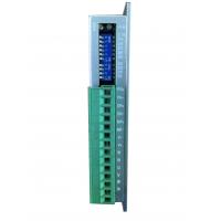
3phase stepper motor driver JB378M DC24-80V 6.0A 300 Microsteps Matching 3phase stepper motor size 57mm and 86mm
Features
High performance, low price
16 channels constant angle and constant torque microstep, max revolution is up to 60,000 pulse/R
Upmost response frequency amounts to 200Kpps
Once the pulse stops over 1.5s, the phase current will be automatically reduced to half of pre-set current
Opto-isolated signal Input/Output
Driving current can be adjusted from 2.5A/phase to 6.0A/phase through 16 channels
Single power input, voltage range: DC24-80V
it can match 3 phase hybrid stepper motors whose current is under 6.0A, flange size ranges from 57mm to 86mm.
Wiring example

Current setting
The working current of the driver is set by D1-D4 terminal, for more details please refer to the diagram below .
Current (A) | 2.5 | 2.7 | 2.9 | 3.0 | 3.5 | 3.7 | 3.9 | 4.2 |
D1 | OFF | OFF | OFF | OFF | OFF | OFF | OFF | OFF |
D2 | OFF | OFF | OFF | OFF | ON | ON | ON | ON |
D3 | OFF | OFF | ON | ON | OFF | OFF | ON | ON |
D4 | OFF | ON | OFF | ON | OFF | ON | OFF | ON |
Current (A) | 4.4 | 4.6 | 4.8 | 5.0 | 5.2 | 5.4 | 5.8 | 6.0 |
D1 | ON | ON | ON | ON | ON | ON | ON | ON |
D2 | OFF | OFF | OFF | OFF | ON | ON | ON | ON |
D3 | OFF | OFF | ON | ON | OFF | OFF | ON | ON |
D4 | OFF | ON | OFF | ON | OFF | ON | OFF | ON |
Microstep setting
The microsteps of the driver are set by D5-D8 terminal with the following 16 channels. The D9 and D10 are for function setting.
Details are as below: Microsteps(pulse/R)
Microstep | 400 | 500 | 600 | 800 | 1000 | 1200 | 2000 | 3000 |
D5 | ON | ON | ON | ON | ON | ON | ON | ON |
D6 | ON | ON | ON | ON | OFF | OFF | OFF | OFF |
D7 | ON | ON | OFF | OFF | ON | ON | OFF | OFF |
D8 | ON | OFF | ON | OFF | ON | OFF | ON | OFF |
Microstep | 4000 | 5000 | 6000 | 10000 | 12000 | 20000 | 30000 | 60000 |
D5 | OFF | OFF | OFF | OFF | OFF | OFF | OFF | OFF |
D6 | ON | ON | ON | ON | OFF | OFF | OFF | OFF |
D7 | ON | ON | OFF | OFF | ON | ON | OFF | OFF |
D8 | ON | OFF | ON | OFF | ON | OFF | ON | OFF |
D9 | ON, Double pulse: PU is clockwise pulse signal, DR is counterclockwise pulse signal | |||||||
OFF, single pulse: PU is step pulse signal, DR is direction signal | ||||||||
D10 | Self detect switch (OFF: accept external signal, ON: the driver is running at 30R/M internal) | |||||||
Note: The microsteps can be customized according to clients’ requirement.
Terminal function
Mark | Function | Notes |
PU+ | Step pulse signal+ | It can connect +5V or +24V, but an extra resistor is needed if it connect +24V |
PU- | DP9=OFF, PU is pulse signal | Effects on falling edge, the motor goes one step as the pulse input change from “high” to “low”. Input resistance is 220Ω. Requirement: low voltage:0-0.5V, high voltage:4-5V, pulse width >2.5μs |
DP9=ON, PU is clockwise pulse signal | ||
DR+ | Direction control signal+ | It can connect +5V or +24V, but an extra resistor is needed if it connect +24V |
DR- | DP9=OFF, DR is direction control signal | Change motor’s direction of rotation. Input resistance is 220Ω. Requirement: low voltage:0-0.5V, high voltage:4-5V, pulse width >2.5μs |
DP9=ON, DR is counterclockwise pulse signal | ||
MF+ | Motor Free signal+ | It can connect +5V or +24V, but an extra resistor is needed if it connect +24V |
MF- | Motor Free signal- | Once effects, it will cut off the motor current, the driver stops working and sets the motor free |
V+ | Power+ | DC24-80V |
V- | Power- | |
NC | NC |
|
U | Connect to the motor |
|
V | ||
W |
! Caution
1. The input voltage can not exceed DC80V.
2. Input control signal is 5V, current-limiting resistance should be connected when it is over 5V.
3. The input pulse signal effects on falling edge
4. ALM lights and the driver stops working when the driver temperature is over 80℃. Until the temperature falls to 50℃, it will restart to work after powered-up. The heat sink is needed when overheat occurs
5. ALM lights if it is short circuit, please check motor leads and eliminate other short faults, and then repower up to restore
6. ALM lights if the motor does not connect well with the driver, please check motor leads and repower up to restore


