
|
|
[China]

Trade Verify
Address: Hengdian Industrial Zone , Zhuzhou Liling City,Hunan Province,China
Contact name:Ivy Zeng

Changsha Kaienli Hydraulic Technology Co., Ltd. |
|
Verified Suppliers
|

|
|
Product Pictures:
KSV08-33L-0-N 3 way plug in hydraulic valve 2 position cartridge solenoid valve
Description: Electromagnetic drive, three-way slide valve, direct acting spool type, hydraulic threaded directional valve
Working principle:
During power outage, KSV08L-30 allows oil to flow from ② to ①,
while
③ Stop at. After being powered on, the valve core of the plug-in
moves, connecting ③ to ②, and stopping the flow of oil from ①. The
oil port ① can be used as an oil inlet, and the pressure cannot
exceed 210Bar. Emergency manual control options
Operation method: To perform emergency operations, please press the
button and rotate it counterclockwise 180 ° before releasing it.
The built-in spring will push the button out. At this position, the
valve may only partially move. To ensure complete emergency
movement, pull the button to its maximum travel and hold it in this
position. To restore normal valve function, press the button and
rotate 180 ° clockwise before releasing. The emergency manual
control option will be locked in this position.


Product technical data:

Product real pictures :


Company Exhibitions:


Our Certificate:


Product processing procedures:

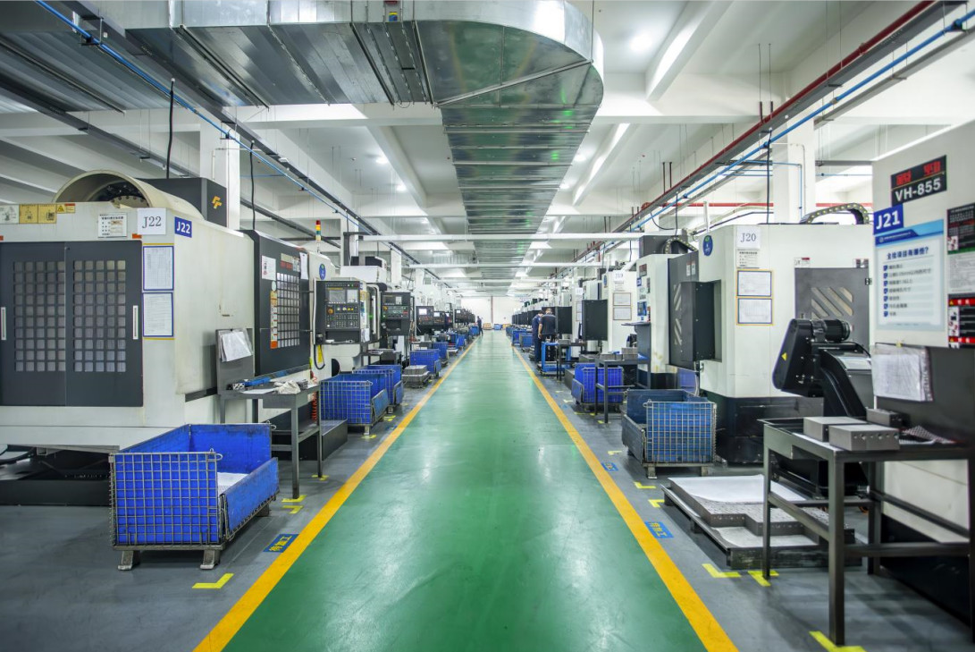
Our new factory and workshop :


Our warehouse:

Shipment:

Different Series of Product , more details please contact us directly:
Hydraulic valves:
1. Relief valves:
Pressure relief valves are installed generally in derivation between a pressurized line and the tank.
Relief valves are normally closed elements for the pressure control used to:
- limit the pressure in the circuit at the setting value;
- protect the other elements (pumps, cylinders, motors, other valves) from pressure peaks that could damage them.
When setting pressure is reached, the relief valve connects the line where is installed to the tank, avoiding to exceed the setting value in that line.
HBS relief valves are available in two versions:
- direct;
- piloted.
For greater flows, it is better to use the piloted valve, because the direct valve would require the use of a bigger body and a bigger spring, causing cumbersome problems, setting difficulty and response slowness.
Moreover, HBS pressure relief valves can be:
- single, to control the pressure on only one line of the circuit.
2.Relief reducing valves:
The pressure reducing valves are used to maintain a reduced pressure in a part of the secondary circuit compared to the inlet pressure of the circuit controlled by a main relief valve. Therefore, if in a circuit with 2 or more cylinders, some of these have to work at a lower pressure than the one set on the main relief valve, by means of this type of valve, it is possible to decrease the operating pressure to the required value. It is normally open valves that, when the pressure on the secondary branch exceeds the value set with the adjusting spring, through a cylindrical spool, go to intercept the flow of oil between the main and secondary branch; in this way, you generate a choke, which reduces the pressure in the output, ensuring the limitation and the maintenance of reduced pressure.
3.Sequence valves:
Sequence valves are elements that open when an established pressure value is reached, allowing the fluid to pass to another part of the circuit. Therefore the opening depends upon the existing upstream pressure. The pressure in the circuit that provokes the opening is kept equal to the setting value, when the valve is open.
When pressure upstream decreases under the setting pressure value, the valve closes.
4.Pilot operate check valves:
Pilot operated check valves are normally used to allow free flow in one direction and to stop the fluid in the opposite one, unless a pilot pressure (Ppil) is applied by the other line of the circuit.
They can be used to ensure the static lock of a load, not for dynamic control or for lowering control.
If used in combination with restrictor valves, these ones should be preferably fitted between the actuator and the pilot operated check valve, not between valve and spool valve, so that the back pressure generated by the restrictor operates against the pilot pressure applied to the valve.
5.Overcenter valves:
Single overcenter valves inline:
Single OVC valves flangeable
Dual overcenter valves in line
DUAL OVC valves flangeable
Dual OVC with regenerative
In the regenerative circuits, the fluid in the rod side of the cylinder is sent to the piston side of the cylinder, regenerating the fluid usually destined to the reservoir. This way, in the piston side, the flow arriving from the rod side is added to the flow arriving from the pump, with a notable increase of the piston speed
This solution is utilised to control cylinders when a lower output stroke time is required without increasing the pump flow.
6.Valves for excavators:
Valves for earth moving machines
They are suitable to be used on excavators machines.
They are used to control the lowering of a load and the pilot pressure depends only from the spring preload and the piston area since they have no differential area.
The pilot pressure is normally achieved simultaneously from the manipulators pressure to drive the main spool valve.
For these valve it is not possible to determine a pilot ratio. They consist in a check valve that can be coaxial with the sealing plunger, a pilot piston and an auxiliary relief valve to cut off overload peaks.
The sealing plunger is piloted by the pressure downloaded by the relief valve. The valve is not affected by any back pressure in the V2 line. In case of damage of the manipulators, the lowering of the load can be performed manually, operating on the proper manual pilot screw.
Line T must be connected to the reservoir and without back pressure.
7.valves for motors:
The overcenter valves are employed to control the stop and the motion of one direction of an actuator (single overcenter valves) or both the directions (dual overcenter valves).
Functions:
- load lowering control: the lowering of the load is possible only if there is a pilot pressure from the other line; this operation ensures the oil supply of the cylinder preventing cavitation problems;
- containing of the pressure at the setting value, pressure relief for any pressure peaks caused by shocks or overloads; - arrest of the flow (and of the load) when the pump is not working or the directional valve is in neutral position;
- free flow for load lifting, with reduced pressure drops;
They consist of a body where are placed:
- check valve: it allows the flow in only one direction;
- pilot piston: it permits to control the gradual opening of the relief valve;
- relief valve: it permits to limit the maximum pressure in the actuator, it withholds the load and controls its lowering during the opening of the valve by the pilot signal.
8.Valves for big cranes
9.Rotation control valves:
Slewing control valves
These valves are utilised to control the stop and the motion of cylinders and hydraulic motors for the rotation of hanging loads. Symmetrical capacity of both the rotation direction is typical of motors and cylinders for this application.
The valves can be composed by:
- dual crossed relief pressure valve: it controls any pressure peaks coming from overloads or shocks that could damage the system components;
- motion speed control valves: for this operation restriction check valves or pressure compensated flow control valves are utilised;
- load hold valves: for this task overcenter valves or check valves are utilised;
- a pressure selecting valve that picks up the signal from the highest pressure side.
10.Hose burst valves:
Hose break valve
These are valves installed in the cylinders connections, their function is to stop the outflow of the fluid in case of hoses breaking. When the flow suddenly increases (reaction flow), the valve closes and stops the flow, ensuring the load to keep the position it had at the break instant.
Setting pressure is obtained settling the gap T between the plate and the body of the valve.
Upon request these valves can be provided with a calibrate hole on the closing plate to control the lowering of the load, or to avoid fluid blasts in the pipes with a little way out of the flow. They are available also already installed inside a steel sleeve.
The setting value of the reaction flow depends also on the fluid viscosity. It is then recommended to set the valve at a 30°C of temperature. During its use, below 30°C, the valve will stop lower flows that the setting flow value, on the contrary, beyond 30°C it will stop higher flows than the setting flow value.
11.Shuttle valves:
These valves select the higher pressure between two lines A and B sending the signal to the C port and locking the way to the lower side.
They are normally used for auxiliary functions such as negative hydraulic brakes, or to drive remote pressure sensing line. In series in a manifold they drive the max pressure of the circuit to the load sensing system.
12.Flow restrictor valves:
The flow restrictor valves allow the adjustment of the flow by a restriction of the main pipe. The exceeding fluid is downloaded by the relief valve that is always installed on the inlet pipe.
They are responsible then of an energy dissipation and heat increasing that could suggest to install a heat exchanger, to limit the max. temperature of the fluid.
They are recommended when the excess of flow is very limited or in low frequency application. Otherwise the use of pressure compensated flow regulator is suggested.
13.Check valves
These valves allow free flow in a direction and stop it in the opposite direction.
They are built in hexagonal bodies made of steel, suitable to be mounted in line with the hoses.
They are available with 3 different setting values: 0.5 bar, 2 bar, 5 bar. Other settings are also possible.
14.Three way flow regulators
These valves are used to regulate the flow in a circuit where the flow, function of the pump speed, can be higher than the flow requested by the circuit itself. Valves are pressure compensated and the flow can be adjusted to a constant value that is not affected by the working pressure of the actuator. In the opposite direction the flow regulators act like normal restrictors, where the flow is a function of the restriction and of the pressure.
15.Flow-dividers / flow combinersd
These valves split the flow coming from one line, to 2 flows equal or proportional to each other. The percentage by which the exit flows are split is function of the valve internal holes diameter, therefore the flow split is not adjustable.
Usually this valve is utilized in the following situations:
- two actuators (with the same dimensions, supplied by the same pump, controlled by the same directional valve, without a rigid link between them) have to move in and out simultaneously, each one without being affected by the load operating on the other one
- for the synchronized exit motion of two linear actuators linked to the same load (for example load platforms, scaffolds, etc.)
16.Diverter valves
These valves are manually operated to divert the inlet flow towards different outlet ports.
The following models are available:
- 5 ways-8 positions diverters
- 9 ways-8 positions diverters
- 8 ways-2 positions diverters
- 3 ways-2 positions diverters
- 4 ways-2 positions diverters with relief valve on one line
- 4 ways-2 positions diverters with a relief pressure valve and a compensated flow regulator on one line.
All valves are produced with a steel manifold.
HBS offers special manual diverters used to switch the inlet flow towards different outlets. They are used, for example, to control the position and the motion of the stabilizing cylinders of the lifting machines (cranes, aerial platforms, etc.). With the dual control is possible to work from both the sides of the machines.
17.End switch valves
These valves are 2 ways 2 position valves, both normal open or
normally closed. These are controlled by a mechanical item that is
activated when the actuator
reaches the defined position. Blocking or allowing the flow.
18.Special valves :
This section offers a large range of valves for different applications:
- 2 ways-2 positions switches;
- 3 ways-2 positions switches;
- unloading valves for emergency systems;
- high-low pressure exclusion valves;
- rotation control valves for special applications;
- integrated block for garbage compactors;
- pilot operated unloading valves;
- sequence valves for load control systems;
- integrated block for load control systems;
- integrated block with kick out pistons;
- purge valve for closed loop hydrostatic systems;
- anti-cavitation valve.
| Type 1 | soloenid valve |
| Type 2 | manual cartridge valve |
| Type 3 | 2 way 2 position solenoid valve |
| Type 4 | 2 way 6 position solenoid valve |
| Type 5 | 2 way 8 position solenoid valve |
| Type 6 | Pilot oil resource valve |
| Type 7 | explosion proof valve |
| Type 8 | balance valve |
| Type 9 | check valve |
| Type 10 | Hydraulic lock |
| Type 11 | Valve manifolds |
| Type 12 | valve block |
Welcome your visit and inquiry !


