|
|
[China]

Trade Verify
Address: Junmin Road, Huangqiao Industrial Park, Taixing, Jiangsu, China (Mainland)
Contact name:jimmy(General Director)

Jiangsu Hanpu Mechanical Technology Co., Ltd |
|
Verified Suppliers
|

|
|
Iodized Salt Crusher Washing Refining Drying Packing equipment of
Whole Salt Production System
Sea Lake Salt Production Line is a set of equipment that our
factory has meticulously developed for crude raw sea salt and lake
salt.
Various capacity is available for buyer's different requirement
(3-30t/h or customized).
Three washing is as follows:
First Screw washing
Stand-up stirring washing
Countercurrent washing
Three crushing is as follows:
First crushing
Wet crushing
Dry crushing
The combination of first crushing, wet crushing and dry crushing
has greatly improved the salt quality. The above operation is
adjustable according to the crude salt and user's requirements on
finished salt quality.
Advantages:
Finished has high purity, shiny appearance, free liquidity and
stable iodine content.
Low loss, the loss of NaCl is under 8%.
Low energy consumption and investment.
Equipment is easy to operate and maintain.
The salt production line begins with raw salt, and consists of the
following:
| 1. Salt feed hopper | 10. Brine tank | 19. Belt conveyor |
| 2. Rationed screw conveyor | 11. Thickener | 20. Sewing sacks |
| 3. Pikcing belt machine | 12. Centrifuge | 21. LCD electronic scale |
| 4. De-ironing separator | 13. Screw conveyor | 22. Chain grate coal-fired hot blast stove |
| 5. Screw washer | 14. Iodine adding machine | 23. Slag discharge machine |
| 6. Roll crsher | 15. Vibration fluidized bed dryer | 24. Coal conveyor |
| 7. Agitating salt wahser | 16. Cyclone dust extractor | 25. Electric control cabinet |
| 8. Slurry pump | 17. Spray washer | 26. Packing machine |
| 9. Agitating tank | 18. Bucket elevator | etc. |
Process Of Salt Refining
(A) Raw salt feeding (B) Salt washing & Milling (C) Dosing
of additives & coating (D) Centrifuging (E) Drying (F) Sizing
& Conditioning (G) Packing (H) Brine recycle
A) Raw salt is fed to the raw salt hopper from the stockyard
or directly unloaded from the dumper. Below this hopper there is a
feeder arrangement. This feeder feeds material to a conveyor. This
conveyor has magnetic separators at the feed and discharge points
to remove iron pieces like nails, nuts and bolts and other magnetic
debris. The conveyor discharges raw salt to the feed hopper of the
wet mill.
B) Wet mill grids and control the size of the product and
also removes soluble entrapped in grained impurities present in the
raw salt crystals. In this process raw salt is milled with brine to
achieve the desired results. Salt slurry from the wet mill falls by
gravity into a slurry tank below. In the slurry tank more brine is
added to carry out primary elutriation. Overflow of the slurry tank
is carried to the settling ponds. Salt slurry is pumped to the wash
tank for main elutriation. The overflow brine from wash tank is
taken into a clarifier for purification and to recycle it back into
the system.
C) Salt slurry from the wash tank is pumped to a thickener
where the slurry is conditioned for centrifuge. This as a dual
purpose tank that also carries our secondary elutriation as well as
thickening of the salt slurry. This slurry is then fed to the
centrifuge. Salt cake from the centrifuge is taken up by a screw
feeder and the mother liquor is discharged to slurry tank below,
D) The salt cake discharged into the screw feeder is dosed
with iodine and other additive anti caking agent before it is
carried to the fluid bed dryer.
E) The fluid bed dryer is an internationally accepted option
for drying salt cake. It is an iIntegrated system involving two
sections for heating and subsequent cooling the product. Hot air is
blown with the help of fan into the salt bed to achieve the
required dryness of final product. Ambient air is blown into the
cooling section to cool the hot may be packed in sacs and sealed.
Salt from the outlet of the dryer is carried up through a bucket
elevator for sizing and conditioning.
F) The dry salt from the bucket elevator is fed to a gyro
screen. Oversize from the screen is sent to a dry mill (pin mill)
for regrinding. The sized product is fed to the blender for
conditioning to make it free flowing or iImparting properties and
composition that may be required. Output from the dry mill is sent
back to the screen to avoid any mixing of oversize with the final
product.
G) Final product from the blender is stored in a silo. These
silos feed the packing machines to pack the final product to pack
the production 1 Kg. to 50 Kg. bulk packing as may be required.
H) Clear brine that overflows from the clarifier is taken to
a brine tank. Sludge that settles in the clarifier is discharged
iInto the settling tank. Brine from the brine tank is pumped into a
brine header. This brine header distributes brine at predetermined
rates to various tanks. Run-off brine from the settling pond is
recovered and pumped by a transfer pump back into the process.
Sludge that settles at the bottom of the pond is scrapped and
disposed off to the salt pans or any other approved site.
Main equipment-Vibrating Fluidized Bed Dryer Features
HP series vibration fluidized bed dryer is driven by the vibration
force caused by vibration motor. The material in a given direction
under the action of the force of leaping forward, at the same time
a bed type cloth uniform wind hot air in a fluidized state of
material, material particles in contact with the hot air fully,
intense heat and mass transfer process, high thermal efficiency,
cavity in the state of the negative pressure, moist air is being
exhausted from induced draft fan, dry material is being exhausted
from port layout, so as to achieve the ideal effect. This machine
is widely used in salt industry of powdery and granular materials
such as operation of drying, cooling and humidifying.
Vibrating Fluidized Bed Dryer Specification
| Model | Fluidized bed area (m × m) | Reference of water evaporation (kg/h) | Rated power (kw) |
| HP - 3 × 4.5 | 0.3 × 4.5 | 40 - 70 | 1.5 × 2 |
| HP - 4 × 4.5 | 0.4 × 4.5 | 65 - 100 | 2.2 × 2 |
| HP - 6 × 4.5 | 0.6 × 4.5 | 80 - 130 | 2.2 × 2 |
| HP - 6 × 6.0 | 0.6 × 6.0 | 120 - 180 | 3.0 × 2 |
| HP - 6 × 7.5 | 0.6 × 7.5 | 150 - 220 | 3.7 × 2 |
| HP - 9 × 6.0 | 0.9 × 6.0 | 160 - 280 | 3.7 × 2 |
| HP - 9 × 7.5 | 0.9 × 7.5 | 180 - 300 | 3.7 × 2 |
| HP - 12 × 7.5 | 1.2 × 7.5 | 300 - 400 | 5.5 × 2 |
| HP - 15 × 7.5 | 1.5 × 7.5 | 350 - 580 | 7.5 × 2 |
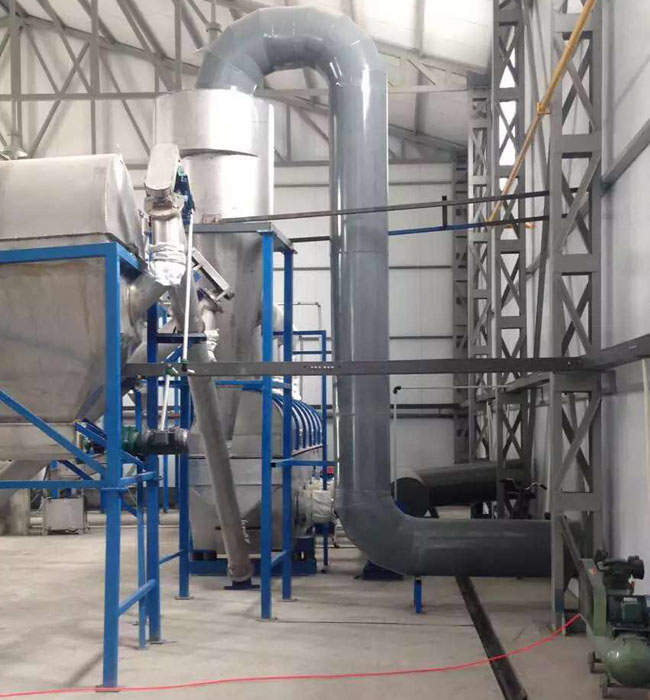
Salt Production flow chart
Client production facility