
|
|
[China]

Trade Verify
Address: Building C, Xinmeijia Science and Technology Park, Chashan
Contact name:Andy Wu

Dongguan Tianrui Electronics Co., Ltd |
|
Verified Suppliers
|
|
|
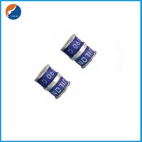
3RB-8S Gas Discharge Tube 75V 90V 150V 230V 250V 350V 420V 470V 600V 10KA 8x10mm GDT Surge Protector Arrester
Description of 3RB-8S Gas Discharge Tube
GDT is placed in front of, and in parallel with, sensitive telecom
equipment such as power lines, communication lines, signal lines
and data transmission lines to help protect them from damage caused
by transient surge voltages that may result from lightning strikes
and equipment switching operations. These devices do not influence
the signal in normal operation. However, in the event of an
overvoltage surge, such as a
lightning strike, the GDT switches to a low impedance state and
diverts the energy away from the sensitive equipment.
Our GDT offer a high level of surge protection, a broad voltage
range, low capacitance, and many form factors including new surface
mount devices, which makes them suitable for applications such as
Main Distribution Frame (MDF) modules, high data-rate telecom
applications (e.g. ADSL, VDSL), and surge protection on power
lines. Their low capacitance also results in less signal
distortion. When used in a coordinated
circuit protection solution with PolySwitch devices, they can help
equipment manufacturers meet stringent safety
regulatory standards.


Electrical Symbol of 10KA 8x10mm GDT Surge Protector Arrester

Features of 10KA 8x10mm GDT 3RB-8S Gas Discharge Tube
• Excellent response to fast rising transients
• Stable breakdown voltage
• GHz working frequency
• 8/20μs Impulse current capability: 10KA
• Non-Radioactive
• Ultra Low capacitance (<1.5pF)
• High insulation resistance
• Lead-free compliant
• RoHS and REACH compliant
• Size: Ф8mm*10mm
• Storage and operational temperature: -40~+90°C
Applications of 3RB-8S Surge Protector Arrester
• Communication equipment
• CATV equipment
• Data lines
• Power supplies
• Telecom SLIC protection
• Broadband equipment
• ADSL equipment, including ADSL2+
• XDSL equipment
• Satellite and CATV equipment
• Test equipment
• Consumer electronics

Electrical Characteristics of 75V 90V 150V 230V 250V 350V 420V 470V 600V Gas Discharge Tube
| Part Number | DC Spark-over Voltage 1) 2) 3) @100V/S | Impulse Spark-over Voltage 3) | Insulation Resistance 4) | Capacitance @1MHz | Life Ratings | ||||||||||||||||||||||||
| Impulse Discharge Current @8/20μs 5) | AC Discharge Current @50Hz 1S 5) | Impulse Life @10/1000μS 200A 5) | |||||||||||||||||||||||||||
| 100V/μS | 1KV/μS | ||||||||||||||||||||||||||||
| Max | Max | Min | Max | Nominal ±5 times | Max 1 time | Nominal 5 times | Min | ||||||||||||||||||||||
| V | V | V | GΩ | pF | KA | KA | A | Times | |||||||||||||||||||||
| 3R075SB-8S | 75±20% | 500 | 600 | 1 | 1.5 | 10 | 20 | 10 | 300 | ||||||||||||||||||||
| 3R090SB-8S | 90±20% | 500 | 600 | 1 | 1.5 | 10 | 20 | 10 | 300 | ||||||||||||||||||||
| 3R150SB-8S | 150±20% | 500 | 600 | 1 | 1.5 | 10 | 20 | 10 | 300 | ||||||||||||||||||||
| 3R230SB-8S | 230±20% | 600 | 700 | 1 | 1.5 | 10 | 20 | 10 | 300 | ||||||||||||||||||||
| 3R250SB-8S | 250±20% | 600 | 700 | 1 | 1.5 | 10 | 20 | 10 | 300 | ||||||||||||||||||||
| 3R350SB-8S | 350±20% | 800 | 900 | 1 | 1.5 | 10 | 20 | 10 | 300 | ||||||||||||||||||||
| 3R420SB-8S | 420±20% | 850 | 950 | 1 | 1.5 | 10 | 20 | 10 | 300 | ||||||||||||||||||||
| 3R470SB-8S | 470±20% | 900 | 1000 | 1 | 1.5 | 10 | 20 | 10 | 300 | ||||||||||||||||||||
| 3R600SB-8S | 600±20% | 1100 | 1200 | 1 | 1.5 | 10 | 20 | 10 | 300 | ||||||||||||||||||||
| Glow Voltage at 10mA ~60V | |||||||||||||||||||||||||||||
| Arc Voltage at 1A....................................................................................... ~10V | |||||||||||||||||||||||||||||
| Glow to Arc transition Current ~1A | |||||||||||||||||||||||||||||
| Operation and storage temperature………………………………..….......... -40~+90°C | |||||||||||||||||||||||||||||
| Climatic category (IEC60068-1) 40/90/21 | |||||||||||||||||||||||||||||
| Weight ~2.0g | |||||||||||||||||||||||||||||
| Surface treatment………………………………………….....…………......... Matte-tin
plated 1) At delivery AQL 0.65 level II, DIN ISO 2859 2) In ionized mode 3) Tip or ring electrode to center electrode 4) Insulation Resistance Measuring Voltage: 75V at DC 25V 90V~150V at DC 50V Other at DC 100V 5) Total current through center electrode, half value through tip respectively ring electrode. Terms in accordance with ITU-T Rec. K.12, IEC 61643-311, GB/T 9043. | |||||||||||||||||||||||||||||

| Symbol | Millimeters | Inches | |||||||||||||||||
| A | 8±0.2 | 0.315±0.008 | |||||||||||||||||
| B | 8±0.2 | 0.315±0.008 | |||||||||||||||||
| C | 10±0.3 | 0.394±0.012 | |||||||||||||||||
| D | Φ8±0.2 | Φ0.315±0.008 | |||||||||||||||||
| E | Φ7.2±0.1 | Φ0.283±0.004 | |||||||||||||||||
| F | 0.5±0.1 | 0.020±0.004 | |||||||||||||||||
| G | 1.5±0.1 | 0.059±0.004 | |||||||||||||||||
| H | 0.5±0.1 | 0.020±0.004 | |||||||||||||||||
| X | 1.5 | 0.059 | |||||||||||||||||
| X1 | 1.5 | 0.059 | |||||||||||||||||
| X2 | 10.0 | 0.394 | |||||||||||||||||
| Y | 6.0 | 0.236 | |||||||||||||||||
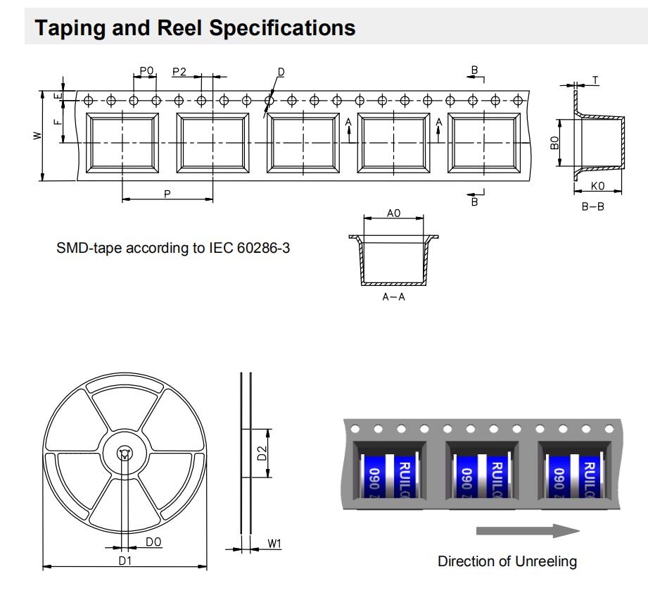
| Symbol | Millimeters | Inches | |||||||||||||||||
| W | 16±0.3 | 0.630±0.012 | |||||||||||||||||
| A0 | 10.5±0.1 | 0.413±0.004 | |||||||||||||||||
| B0 | 8.3±0.1 | 0.327±0.004 | |||||||||||||||||
| K0 | 8.4±0.1 | 0.331±0.004 | |||||||||||||||||
| P | 16±0.1 | 0.630±0.004 | |||||||||||||||||
| F | 7.5±0.1 | 0.295±0.004 | |||||||||||||||||
| E | 1.75±0.1 | 0.069±0.004 | |||||||||||||||||
| D | 1.5+0.1/-0.0 | 0.059+0.004/-0.0 | |||||||||||||||||
| P0 | 4±0.1 | 0.157±0.004 | |||||||||||||||||
| P2 | 2±0.1 | 0.079±0.004 | |||||||||||||||||
| T | 0.4±0.1 | 0.016±0.004 | |||||||||||||||||
| D0 | 13.3±0.15 | 0.524±0.006 | |||||||||||||||||
| D1 | 330±2 | 12.992±0.079 | |||||||||||||||||
| D2 | 100+1/-2 | 3.937+0.039/-0.079 | |||||||||||||||||
| W1 | 16.5±0.4 | 0.65±0.016 | |||||||||||||||||
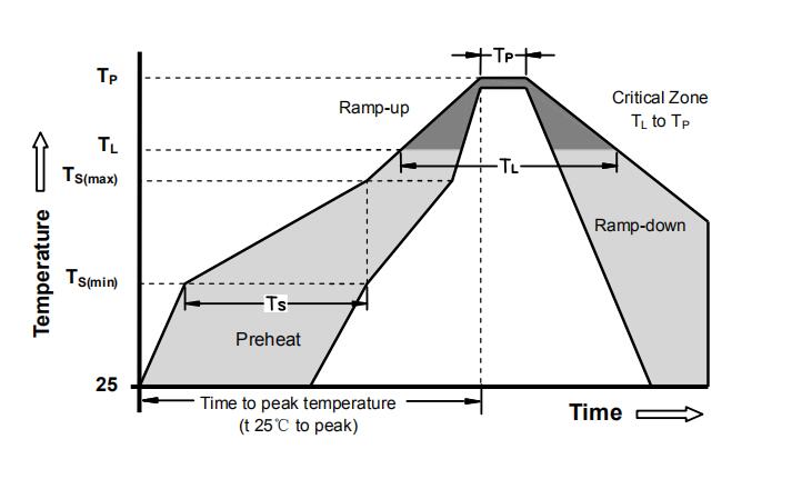
| Reflow Condition | Pb - Free assembly | ||||||||||||||||||||
| Pre Heat | -Temperature Min (Ts(min)) | 150°C | |||||||||||||||||||
| -Temperature Max (Ts(max)) | 200°C | ||||||||||||||||||||
| - Time (min to max) (ts) | 60 -180 Seconds | ||||||||||||||||||||
| Average ramp up rate ( Liquids Temp TL) to peak | 3°C/second max | ||||||||||||||||||||
| TS(max) to TL - Ramp-up Rate | 5°C/second max | ||||||||||||||||||||
| Reflow | - Temperature (TL) (Liquids) | 217°C | |||||||||||||||||||
| - Time (min to max) (ts) | 60 -150 Seconds | ||||||||||||||||||||
| Peak Temperature (TP) | 260 +0/-5°C | ||||||||||||||||||||
| Time within 5°C of actual peak Temperature (tp) | 10 - 30 Seconds | ||||||||||||||||||||
| Ramp-down Rate | 6°C/second max | ||||||||||||||||||||
| Time 25°C to peak Temperature (TP) | 8 minutes Max | ||||||||||||||||||||
| Do not exceed | 260°C | ||||||||||||||||||||


