
|
|
[China]

Trade Verify
Address: 27P , Block B , Duhui 100 , Zhonghang Road , Futian District , Shenzhen , China
Contact name:Biona

Hontai Machinery and equipment (HK) Co. ltd |
|
Verified Suppliers
|
|
|
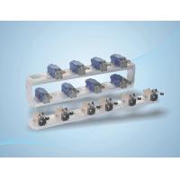
DWG vane position switch, the stroke switch is fixed on the sliding block , offer switch quantity signal
Range : 80~1500mm
Output : 6 mechanical switch
Contact capacity : 250VAC 5A 24VDC 1A
Mounting type : Bracket
Mounting and maintenance :


 DWG vane position switch inlet stroke switch, guide, slider,
installation bracket, the stroke switch is fixed on the sliding
block, according to the requirements of users will switch setting
in the corresponding position, switch quantity signal of guide vane
position, the number of switches can be set according to user
requirements, this product has the advantages of simple structure,
convenient installation and adjustment. After the measurement
point, the position will not change, high reliability, good
stability, long service life of the.DWG guide vane position switch
structure shown in Figure 1, through the installation of fixed
bracket is fixedly connected with the 1 turbine relay device,
switch 2 and 3 sliding blocks are fixed together, a sliding block 3
in the rail 4 when free sliding. Need a guide vane in a position
signal, the switch slide along the relay device, a push-pull rod
block is the travel switch, a signal switch, switch position
adjustment, the locking screw 5 slide fastening. By 3. Fixed
bracket 1 and turbine servomotor is fixedly connected with the
slider, the stroke switch 2 3 fixed together, 3 slide on the guide
rail 4 slide freely, when need to send the guide vane in a position
signal, the switch slide along the relay device, a push-pull rod
block is the trip switch a switch, switch position signal, after
adjustment, the locking screw 5 slider 3 fastening.
DWG vane position switch inlet stroke switch, guide, slider,
installation bracket, the stroke switch is fixed on the sliding
block, according to the requirements of users will switch setting
in the corresponding position, switch quantity signal of guide vane
position, the number of switches can be set according to user
requirements, this product has the advantages of simple structure,
convenient installation and adjustment. After the measurement
point, the position will not change, high reliability, good
stability, long service life of the.DWG guide vane position switch
structure shown in Figure 1, through the installation of fixed
bracket is fixedly connected with the 1 turbine relay device,
switch 2 and 3 sliding blocks are fixed together, a sliding block 3
in the rail 4 when free sliding. Need a guide vane in a position
signal, the switch slide along the relay device, a push-pull rod
block is the travel switch, a signal switch, switch position
adjustment, the locking screw 5 slide fastening. By 3. Fixed
bracket 1 and turbine servomotor is fixedly connected with the
slider, the stroke switch 2 3 fixed together, 3 slide on the guide
rail 4 slide freely, when need to send the guide vane in a position
signal, the switch slide along the relay device, a push-pull rod
block is the trip switch a switch, switch position signal, after
adjustment, the locking screw 5 slider 3 fastening.


