

Active Member
|
[China]

Address: No. 12, Chuangxing Road, Baisha, Humen Town, Dongguan, Guangdong, China
Contact name:Calin Deng

GUANGDONG RUIHUI INTELLIGENT TECHNOLOGY CO., LTD. |

|
|
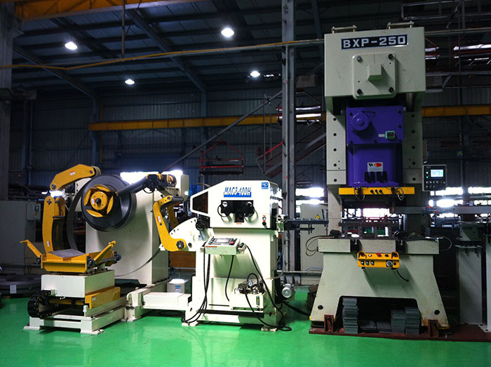
The CNC feeder is short for digital control and is an automation
with a program control system. The control system can logically
process and decode the program with control code or other symbolic
instructions to operate the CNC bending machine and machine the
part.
CNC feeders are used in a wide range of applications. Nowadays, in
the electronic age, many companies have chosen more efficient
machinery to increase productivity.
The function of the servo system is to convert the construction
number of the pulse letter CNC feeder from the numerical control
device into the motion of the moving part. Specifically, the
following components are constructed: the construction of the
numerical control feeder.
1. Auxiliary device: Some necessary supporting components of the
index-controlled feeder to ensure the operation of the CNC feeder,
such as cooling, chip removal, lubrication, lighting, monitoring,
etc. It includes hydraulic and pneumatic devices, chip removal
devices, exchange tables, CNC turntables and CNC indexing heads, as
well as tools and monitoring and inspection devices.
2. the drive device: he is the drive component of the CNC feeder actuator, including the spindle drive unit, feed unit, spindle
motor and feed motor. He drives the spindle and feed through an
electrical or electro-hydraulic servo system under the control of a
numerical control unit. When several feeds are linked, the
positioning, straight line, plane curve and space curve can be
processed.
3. the host: he is the main body of the CNC feeder, including body
parts, columns, spindles, feed mechanisms and other mechanical
components. He is a mechanical component for performing various
cutting operations.
Programming and other ancillary equipment: can be used to program,
store, etc. parts outside the machine.
4. Numerical control device: It is the core of the CNC feeder. It
includes hardware and corresponding software for inputting digital
part programs, and completes input information storage, data
conversion, interpolation calculation and various control
functions.
Specification:
| Model | MAC2-400 | MAC2-500 | MAC2-600 | MAC2-800 | ||
| Stock Width(mm) | 50-400 | 50-500 | 50-600 | 50-800 | ||
| Stock Thickness(mm) | 0.3~3.2 | 0.3-3.2 | 0.3-3.2 | -3.2 | ||
| Max.Coil Weight(kg) | 3000 | 3000 | 3000 | 5000 | 5000 | 7000 |
| Max.Coil O.D.(mm) | 1200 | 1200 | 1200 | |||
| Coil I.D.(mm) | 8 | 8 | 508 | 508 | ||
| Feed Length(mm) | ~500* | ~500* | ~500* | ~500* | ||
| Max. Line Speed(m/min) | 16-24 | 16-24 | 16-24 | 16-24 | ||
| Work Roll Number(pieces) | upper 6 lower 5 | upper 6 lower 5 | upper 6 lower 5 | upper 6 lower 5 | ||
| Feed Roll Number(set) | 1 | 1 | 1 | 1 | ||
| Main Motor(kw) | AC2.9 | AC2.9 | AC4.4 | AC4.4 | ||
| Mandrel Expansion | hydraulic | hydraulic | hydraulic | hydraulic | ||
| Reel Motor(kw) | 1.5 | 1.5 | 1.5 | 2.2 | 2.2 | 3.7 |
| Power(V) | 3 Phase 220V/380V/50HZ | |||||
| Operating Air(Mpa) | 0.49 | 0.49 | 0.49 | 0.49 | ||
Straigtening performance:
| tock Thicknees (mm) | Stock Width (mm) | |||
| 0.3 | 400 | 500 | 600 | 800 |
| 0.4 | ||||
| 0.6 | ||||
| 0.8 | ||||
| 1.0 | ||||
| 1.2 | ||||
| 1.4 | ||||
| 1.6 | 470 | 470 | ||
| 1.8 | 400 | 400 | ||
| 2.0 | 360 | 360 | ||
| 2.3 | 300 | 300 | 300 | 300 |
| 2.5 | 230 | 230 | 230 | 230 |
| 2.8 | 150 | 150 | 150 | 150 |
| 3.2 | 110 | 110 | 110 | 110 |
*1:(Pneumatic):Option in case of pneumatic mandrel expansion is
provi
![]()


