|
|
[China]

Trade Verify
Address: No. 2 Funing, Zhengcheng 1st Road, Xintian Community, Fuhai Street, Baoan District, Shenzhen City, China
Contact name:JOHN CAO

Shenzhen Go-Gold Motor Co., Ltd. |
|
Verified Suppliers
|
|
|
Description
Support power/voltage/revolution customization
Basic parameters
| Voltage(V): | 24V | Torque(Nm): | 1.5Nm |
| Input power(W): | 30W | Current(A): | 1A |
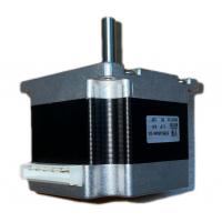
Outline Drawing

Stepper Motor Control We have seen previously that the motor coils
need to be energized, in a specific sequence, to generate the
magnetic field with which the rotor is going to align. Several
devices are used to supply the necessary voltage to the coils, and
thus allow the motor to function properly. Starting from the
devices that are closer to the motor we have: A transistor bridge
is the device physically controlling the electrical connection of
the motor coils. Transistors can be seen as electrically controlled
interrupters, which, when closed allow the connection of a coil to
the electrical supply and thus the flow of current in the coil.
One transistor bridge is needed for each motor phase. A predriver
is a device that controls the activation of the transistors,
providing the required voltage and current, it is in turn
controlled by an MCU. An MCU is a microcontroller unit, which is
usually programmed by the motor user and generates specific signals
for the pre-driver to obtain the desired motor behavior. Figure 7
shows a simple representation of a stepper motor control scheme.
The pre-driver and the transistor bridge may be contained in a
single device, called a driver. Figure 7: Motor Control Basic
Scheme Stepper Motor Driver Types There are different stepper motor
drivers available on the market, which showcase different features
for specific applications.