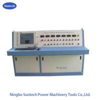
Power Frequency AC Resonant Withstand Voltage Test Set , Power
Frequency Resonant Intelligent Control Unit
I. Product Description :
CHXT (L) series power frequency resonant intelligent control
system, based on the manual control system, carried out by the IPC
with PLC control, set the operation, control, monitoring and
protection in one of the intelligent control system.
Combined with power frequency series resonant system, this system
can do fully automatic completion AC voltage withstand test to
various generating units, Assembling Capacitor, power cables and
GIS, CT, insulators, insulation tools, busbar and so on. in the
power equipment manufacturers
II. Appication and usage
- The measurement and control unit for Power Frequency AC resonant
withstand voltage test circuit.
- Replace the old traditional console to increase the efficiency of
high-voltage test and enhance monitoring and protection during
resonant withstand voltage testing.
III. Main Components of the unit:
- Intelligent Resonance Control console
- Electric voltage regulator cabinet
- PLC computer (built-in designed or external layout designed
,optional)
- Connection cables group
- External alarm lights
IV. Main functions:
1. Perfect manipulative function:
- Programmable auto-test function
- Auto resonant-point searching
- Resonant-point tracing function during step-up
- HV-limiting function
- Tracing function during voltage withstand
- Manual intervention at any time during auto test
- Variable control of step-up speed with the speed range of 2~5Kv/s
2. Date measurement and display function
Display items:
① Power voltage, current;
② Output voltage, current of voltage regulation;
③Voltage of HV side;
④ Clearance of iron core;
⑤ Q Value;
⑥ COSø Value Harmonic degree;
⑦u→t curve.
3. Self-checking for real-status and display function
- Displaying its own manipulation is to facilitate the user to
monitor. During the test, it is automatically monitored the run
situation by the PLC, and once any fault it stops for processing.
4. Protective function
- Fiber-optical communication isolation
- Flashover protection
- Over-voltage protection
- HV sampling lost protection
- HV limiting protection
- Emergency brake protection
5. Data management function
- Database in the system can retain various historical test data.
Flexible and simple search facilitate users to judge the status of
the test object on history data and create the file of test object.
V. General Technical data:
- Mode of resonant circuit: Series resonant with variable inductance
- System model : made by order
- Input power supply : 380±10%(single-phase),50Hz/60Hz
- Rated output capacity: made by order
- Rated output Voltage:made by order
- Rated output current: made by order
- Reg. Freq range : 50/60Hz
- Output Resonance voltage waveform: pure sine wave
- THD of output waveform: ≤1%
- Insulation level: Under 1.1 times and keeping 1min, normal
- Duty cycle : 180mints on under rated current working condition ;
- Noise level: No more than 65dB
- Reactor Structure: oil-immersed with iron tank type ,adjustable
inducatance
VI. Functions description
- Remote control and indication function for the iron-core gap of
reactor:The gap sensor is installed in the reactor, which directly
reads the iron-core gap on the console to guide operation. The gap
limiting switch and indicator are also installed.
- Auto step down function when withstanding time is up:Withstanding
timing adopts digimatic timer. When withstanding time is up, the
system will auto step down.
- Zero position close, zero start step up function:With zero limiting
function. If the voltage regulator is not at zero position, then
the HV output button cannot be closed, assuring the system step up
from zero.
- Over current protection:The system is with over current relay,
which is of high anti interference, fast action, protection test
object against over-current damage.
- Over voltage and test object flash-over protection functions:This
system takes electronic over voltage and flash-over protection
board, protects test object against over voltage and flash-over. It
is fast, stable and reliable, overcoming the instability, large
discreteness and inconvenient adjustment of sphere-gap protection
voltage. The setting of over voltage protection is manual
adjustment, digital display, which is direct, convenient and
accurate. The flash-over protection samples the accident variance
of discharging signal falling delay, compares it with basic signal
and determines. It is of high accuracy, avoiding possible mistake
movement by accident variance of rising delay.
- Real-time monitor function for test data:It is able to monitor HV
side voltage, current and LV side voltage, current, which is more
direct viewing the test status.
- Digital display of circuit resonance and locking function when it
is not of resonance and step up:
- It can directly display the resonance status of the system by power
factor. If the system is not at the resonant point, it must press
close button to step up. When the system is adjusted to resonance,
release the close button, click on the step up/down button to step
up or step down.
- Emergency stop :“Step on” emergency brake switch. Once there is
abnormal conditions during test, step on this switch, the main
power will be cut off right away to protect the safety of the
testing personnel and the equipment.