Active Member
|
[China]

Address: Industry Park. JS, ZJ, China. 314100
Contact name:Tiffany

VIIPLUS INTERNATIONAL |

|
|
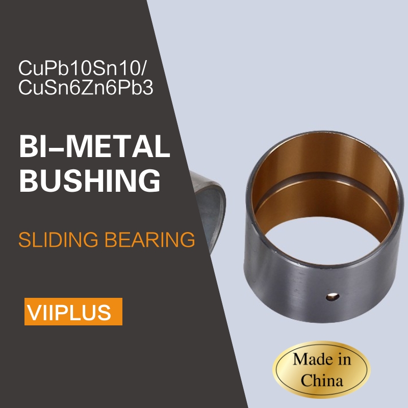
When it comes to engineering applications that require high-performance bushings for track rollers, bimetal bushings made from Cupb10Sn10 and Cusn6Zn6Pb3 materials are an excellent choice. These bushings offer superior wear resistance, corrosion protection, and durability, making them suitable for a wide range of industrial applications.
Cupb10Sn10 is a leaded tin bronze alloy that possesses exceptional wear resistance and good machinability. Its composition allows it to withstand heavy loads and maintain stability under high temperatures. This material is often used in bimetal bushings as the friction-bearing layer, providing a smooth and reliable surface for track rollers to rotate on.
Cusn6Zn6Pb3, on the other hand, is a leaded brass alloy that offers excellent corrosion resistance and good bearing properties. Its combination of strength, toughness, and corrosion resistance makes it a suitable material for the backing layer of bimetal bushings. The backing layer provides structural support to the friction-bearing layer and ensures the overall stability and durability of the bushing.
Track roller bushings made from Cupb10Sn10 and Cusn6Zn6Pb3 materials offer several advantages. Firstly, they have a long service life due to their excellent wear resistance and corrosion protection. This reduces the need for frequent maintenance and replacement, saving time and money. Secondly, their smooth and reliable performance ensures that track rollers operate efficiently and with minimal friction. This leads to improved machine efficiency and reduced energy consumption.
In conclusion, Cupb10Sn10 and Cusn6Zn6Pb3 material track roller bushings are an excellent choice for engineering applications that require high-performance bushings. Their superior wear resistance, corrosion protection, and durability make them suitable for a wide range of industrial applications.
Engineering / Bimetal Bushings / Material Cupb10sn10 & Cusn6zn6pb3 Track Roller Bushes
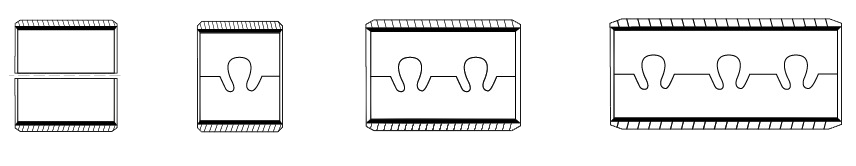
Steel backing with CuPb10Sn10 or CuSn6Zn6Pb3 liners. This grade is best applied in lubricated pin bushings for
application in suspensions, off road construction equipment, auto
chassis points and areas.Bimetal backed system that is self-lubricating and is used in the most rigorous applications.
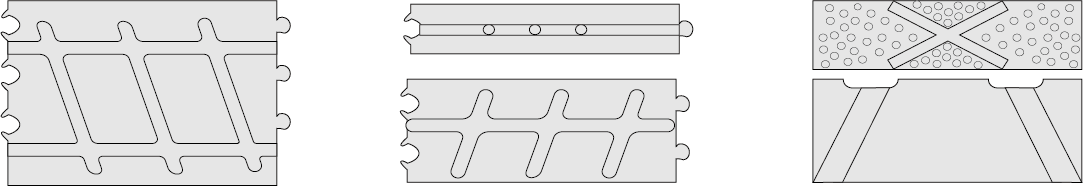
Bimetal bearings utilize special bronze liners for self-lubrication
and
improved wear properties. Each material has a specific wear rate dependent on the speed,
load, temperature, lubrication and hardware of the application. The
steel bronze metal backing supports liner materials made to
withstand high loads, speeds and adverse environments.The advantage
of the bimetal bushes design is that even if wear-thru occurs in
the liner, thesupporting bimetal materail technical is a
self-lubricating material as well.
Steel backing with CuPb10Sn10
or CuSn6Zn6Pb3 liners. Thisgrade is best applied in lubricatedpin
bushings for application in suspensions, off road construction
equipment, auto chassis points and areas where speeds are medium
range but high impact is possible. Load capacity is 10,000 psi,
speed 900 fpm. Hardness: HB70-100 Temperature: -40 to +500F
| CuPb10Sn | ||||
| Pb(%) | Fe(%) | Ni(%) | Zn(%) | Cu(%) |
| 8.0-11.0 | ≦0.25 | ≦1.5 | ≦2.0 | 78.0-87.0 |
| CuPb24Sn4 | ||||
| Pb(%) | Sn(%) | p(%) | Mn(%) | Cu(%) |
| 19~27 | 3~5 | ≦0.08 | ≦0.3 | 67~77 |
| Maximum dynamic load | 140P N/mm² | MAX Temperature°C | Grease lubrication | 150°C | |
| Maximum linear velocity | Grease lubrication | 2.5Vm/s | Fluid lubrication | —— | |
| MAX PV | 2.8N/mm². m/s | Match the diameter of axle | HRC | ≥ 53 | |
| μ | 0.05~0.15 | Ra | 0.32~0.63 | ||
| Maximum linear velocity | Fluid lubrication | —— | Alloy layer hardness | 80~120 | |
| MAX PV | —— | Coefficient of thermal conductivity | 47W/mk | ||
| μ | —— | Linear expansion coefficient (axial) | 18×10-6/K | ||
d | D | 相配轴径 公差( h8) | 相配座孔 公差(H7) | 压入H7座孔 内径公差 | Wall thickness 壁厚 | 注油孔 | f1 | f2 | L 0 -0.40 | ||||||||
min | max | 10 | 15 | 20 | 25 | 30 | 40 | 50 | 60 | ||||||||
10 | 12 | 10-0.022 | 12+0.018 | +0.148 +0.010 | 0.995 | 0.935 | 4 | 0.5 | 0.3 | 1010 | 1015 | 1020 | |||||
12 | 14 | 12-0.027 | 14+0.018 | 1210 | 1215 | 1220 | |||||||||||
14 | 16 | 14-0.027 | 16+0.018 | 1410 | 1415 | 1420 | |||||||||||
15 | 17 | 15-0.027 | 17+0.018 | 1510 | 1515 | 1520 | |||||||||||
16 | 18 | 16-0.027 | 18+0.018 | 0.8 | 0.4 | 1610 | 1615 | 1620 | |||||||||
18 | 20 | 18-0.027 | 20+0.021 | +0.151 +0.010 | 1810 | 1815 | 1820 | 1820 | |||||||||
20 | 23 | 20-0.033 | 23+0.021 | +0.181 +0.020 | 1.490 | 1.430 | 2010 | 2015 | 2020 | 2020 | |||||||
22 | 25 | 22-0.033 | 25+0.021 | 6 | 2210 | 2215 | 2220 | 2220 | |||||||||
24 | 27 | 24-0.033 | 27+0.021 | 1.0 | 0.5 | 2410 | 2415 | 2420 | 2420 | 2430 | |||||||
25 | 28 | 25-0.033 | 28+0.021 | 2515 | 2520 | 2520 | 2530 | ||||||||||
26 | 30 | 26-0.033 | 30+0.021 | +0.205 +0.030 | 1.980 | 1.920 | 2615 | 2620 | 2620 | 2630 | |||||||
28 | 32 | 28-0.033 | 32+0.025 | 2815 | 2820 | 2820 | 2830 | 2840 | |||||||||
30 | 34 | 30-0.033 | 34+0.025 | 1.2 | 0.6 | 3015 | 3020 | 3020 | 3030 | 3040 | |||||||
32 | 36 | 32-0.039 | 36+0.025 | 3215 | 3220 | 3220 | 3230 | 3240 | |||||||||
35 | 39 | 35-0.039 | 39+0.025 | 3520 | 3520 | 3530 | 3540 | 3550 | |||||||||
38 | 42 | 38-0.039 | 42+0.025 | 8 | 3820 | 3820 | 3830 | 3840 | 3850 | ||||||||
40 | 44 | 40-0.039 | 44+0.025 | 4020 | 4020 | 4030 | 4040 | 4050 | |||||||||
d | D | 相配轴径公差(h8) | 相配座孔公差(H7) | 压入H7座孔内径公差 | Wall thickness 壁厚 | 注油孔 | f1 | f2 | L 0 -0.40 | ||||||||
min | max | 25 | 30 | 40 | 50 | 60 | 80 | 90 | 100 | ||||||||
45 | 50 | 45-0.039 | 50+0.025 | +0.205 +0.030 | 2.460 | 2.400 | 8 | 1.5 | 1.0 | 4525 | 4530 | 4540 | 4550 | ||||
50 | 55 | 50-0.039 | 55+0.030 | +0.210 +0.030 | 5030 | 5040 | 5050 | 5060 | |||||||||
55 | 60 | 55-0.046 | 60+0.030 | 5530 | 5540 | 5550 | 5560 | ||||||||||
60 | 65 | 60-0.046 | 65+0.030 | 6030 | 6040 | 6050 | 6060 | ||||||||||
65 | 70 | 65-0.046 | 70+0.030 | 6530 | 6540 | 6550 | 6560 | ||||||||||
70 | 75 | 70-0.046 | 75+0.030 | 7030 | 7040 | 7050 | 7060 | 7080 | |||||||||
75 | 80 | 75-0.046 | 80+0.030 | 9.5 | 7530 | 7540 | 7550 | 7560 | |||||||||
80 | 85 | 80-0.046 | 85+0.035 | +0.215 +0.030 | 8040 | 8050 | 8060 | 8080 | |||||||||
85 | 90 | 85-0.054 | 90+0.035 | 8530 | 8550 | 8560 | 8580 | 85100 | |||||||||
90 | 95 | 90-0.054 | 95+0.035 | 9050 | 9060 | 9080 | 90100 | ||||||||||
95 | 100 | 95-0.054 | 100+0.035 | 9060 | 9080 | 9090 | 90100 | ||||||||||
100 | 105 | 100-0.054 | 105+0.035 | 10060 | 10080 | 10090 | 100100 | ||||||||||
105 | 110 | 105-0.054 | 110+0.035 | 10560 | 10580 | 105100 | |||||||||||
110 | 115 | 110-0.054 | 115+0.035 | 11060 | 11080 | 110100 | |||||||||||
115 | 120 | 115-0.054 | 120+0.035 | 11550 | 11580 | ||||||||||||
120 | 125 | 120-0.054 | 125+0.040 | +0.220 +0.030 | 12050 | 12060 | 120100 | ||||||||||
125 | 130 | 125-0.063 | 130+0.040 | 125100 | |||||||||||||
130 | 135 | 130-0.063 | 135+0.040 | 13060 | 130100 | ||||||||||||
135 | 140 | 135-0.063 | 140+0.040 | 13560 | 13580 | ||||||||||||
140 | 145 | 140-0.063 | 145+0.040 | 14060 | 14080 | 140100 | |||||||||||
150 | 155 | 150-0.063 | 155+0.040 | 15060 | 15080 | 150100 | |||||||||||
| Norminal Thiickness | Tolerances of Series B (non-machinable) | Tolerances of Series C (non-machinable) |
| 1.0 | -0.025 | +0.25 +0.15 |
| 2.0 | -0.030 | +0.25 +0.15 |
| 2.5 | -0.035 | +0.25 +0.15 |
| 3.0 | -0.040 | +0.30 +0.15 |
| 3.5 | -0.045 | +0.30 +0.15 |
| 3.5 | -0.050 | +0.30 +0.15 |