
|
|
[China]

Trade Verify
Address: No.8 Tianshan road, Xinbei district,Changzhou,Jiangsu,China.
Contact name:Amigo Deng

Changzhou Bextreme Shell Motor Technology Co.,Ltd |
|
Verified Suppliers
|
|
|
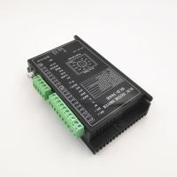
Brief introduction
BLD-300B is designed by Changzhou Bextreme Shell motor technology and mainly for BLDC motors
( 48v: 440w /24V:300w)
Features:
Acc/Dec time setting
Alarm indication
Peak current setting
Pole-pairs selection
Open/closed loop control
External potentiometer speed setting
Max output current P-sv setting
External analog signal speed setting
PWM speed setting
Electrical Performance
Driver parameter Min Value Typical Value Max Value
Voltage input DC (V): 12 ,24V,36V,48V ,56
Current output(A) : 15
Motor speed range(rpm) : 20000
Hall signal voltage(V) : 5
Hall drive current (mA): 12
External potentiometer(KΩ) : 10
Dimension (Unit: mm)

Function setting
1. Motor poles pair selection

SW1 is for motor poles pair selection to match different
BLDC motor. ON=2P; OFF=4P
2. Open/Closed loop setting
SW2 ON=Closed loop setting; SW2 OFF=Open loop setting

3. Peak current setting
Use P-sv to set the output peak current. When load is increased suddenly, the output
current will be limited by the setting value, which reduces motor speed and protects the
motor. Current setting ranges: 3-15A. Please set as the right.
As the admissible error of real current and setting value is ±10%, to ensure safety, set
current lower accordingly.

4. ACC/DEC time setting
Set acceleration time and deceleration time by ACC/DEC, range is 0.3-15s. Acceleration
time is time needed from 0 to rated speed. Deceleration time is time needed from rated
speed to 0.

Port signal description
Signal category
Terminal Functional Description
Control signal
BRK:Motor brake stop control signal; BRK and COM connect in default,
motor brake stops when BRK and COM disconnect.
EN:Stop signal terminal;EN connects COM, motor runs, otherwise
motor stops.
F/R:Motor direction control terminal; F/R and COM disconnect, motor
will rotates clockwise, and otherwise, motor will rotate
anticlockwise.
COM:Common port(GND)
SV
① External potentiometer speed setting input;
② External analog voltage input terminal
③ PWM speed setting input
Hall signal
REF+ Hall sensor signal power supply+
HU Hall sensor signal Hu
HV Hall sensor signal Hv
HW Hall sensor signal Hw
REF- Hall sensor signal-
Motor connection
W Motor line W phase
V Motor line V phase
V Motor line U phase
Powerconnection
DC+ Power supply positive electrode (18-50VDC)
DC- Power supply negative electrode (Hall sensor negative electrode)
Outputsignal
SPEED Outputpulse frequency corresponded with running speed. Speedcan be figured out
according:
N(rpm)= (F/P)×60/3
F:Output pulse frequency P: Motor pole pairs N: Motor speed
For example: Motor has 4 pole pairs,
F=1sec/2ms=500Hz
N(rpm)=(500/4)×60/3=2500
ALM:Motor or driver fault signal output. It is 5v in normal situation and
0V when faultoccurs.
Driver interface and wiring diagram

Speed setting methods and setting
1. Speed setting via built-in potentiometer
Motor speed increases when RV knobs is rotated clockwise, when anticlockwise, motor
speed decreases.

2. Speed setting via external potentiometer
Use a suitable potentiometer with a resistance value of 10KΩ; when connect external
potentiometer, the middle terminal connects to SV, the other two terminals connect to
REF+ and COM.
Notice: 1. RV should be rotated anticlockwise to limit position.

3. Speed setting via external analog signal 0-5V
The analog signal voltage can be 0 ~ 5VDC; when the voltage is 0.2VDC, the motor
speed reaches 4% of fastest speed; when the voltage is 5 VDC, the motor speed reaches
maximum value, which depends on the motor specification and power voltage.


4.PWM Speed setting (5V PWM, 1-3KHz)
When duty ratio of pulse is 4%, motor speed is 4% of max speed, when duty ratio is 100%,
motor reaches max speed. The max speed also depends on the motor specification and
power voltage.


