
|
|
[China]

Trade Verify
Address: RM C, 13/F, HARVARD COMMERCIAL BUILDING, 105-111 THOMSON ROAD, WAN CHAI, HK
Contact name:Lynette Wong

KingPo Technology Development Limited |
|
Verified Suppliers
|

|
|
Impulse test generator circuit 2 of Table D.1.

1950S pulse generator, is a test instrument for generating pulse
signal and HVDC signal. This instrument is designed and
manufactured according to Appendix N.1 of GB4943.1-2011
(IEC60950-1:2005,MOD) ( IEC62368-1-2018 ) standard. It simulates
lightning interference in communication network and transient
voltage in distribution system for all kinds of information
technology equipment. It belongs to electrical safety test
instrument and equipment. The 1950 S pulse generator is controlled
by Panasonic PLC programmable controller (FP-X C14R).
All parameters and The working state of the instrument is displayed
and set on the 7-inch color touch screen (TK6070iH) , and the menu
interface between Chinese and English is provided.
The instrument also has over-voltage protection to ensure the
safety and reliability of the instrument, and can be widely used in
electrical safety testing laboratories and electronic and
electrical manufacturing enterprises.
Parameter:
1. Test pulse waveform: 10/700uS
The waveform error is ±20%
The output pulse voltage is 0 ~ 4kV, which can be adjusted
continuously
The accuracy of voltage digital display is ±5% ±3 words
2. Test pulse waveform: 1.2/ 50uS
The waveform error is ±20%
The output pulse voltage is 0 ~ 6kV, which can be adjusted
continuously
The accuracy of voltage digital display is ±5% ±3 words
3. Charge and discharge time setting: 1 second ~ 999 seconds
4. Its accuracy is ±1%
5. Charge and discharge times set: 0 ~ 999 times
6. Its accuracy is ±1.
7. Output voltage polarity: positive and negative alternating
switching
8. The partial voltage ratio of the monitoring output is 1 ≤ 1000
9. Overcurrent protection and overvoltage protection can be
continuously set protection values
(in-machine adjustment settings)
10. Display and operation mode: 7 inch color touch screen
(TK6070iH) display and menu interface
operation;
11. High voltage transformer power: 400VA
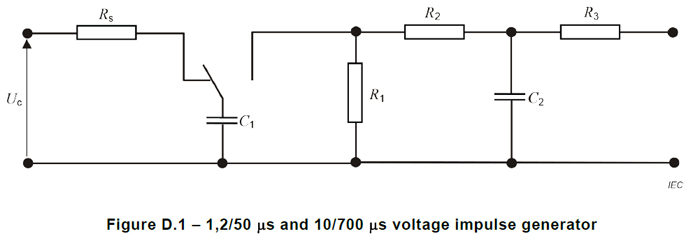
| Circuit type | Test pulse | C1 | C2 | R1 | R2 | R3 |
| 1 | 10/700us | 20uF | 0.2uF | 50Ω | 15Ω | 25Ω |
| 2 | 1.2/50us | 1uF | 30nF | 76Ω | 13Ω | 25Ω |
| remarks | If the same results can be obtained, an alternative test generator can be used. Note: circuit 1 and circuit 2 are based on ITU-T Recommendation K.44 | |||||
Note:
(1)The circuit in the figure above is used to generate pulse
voltage, and the values of the components used are shown below. The
starting state of capacitor C1 is charged voltage Uc.10/ 700 μ s
(10 μs is apparent wavefront time, 700 μ s is apparent half peak
time, its waveform is shown in figure 9, T1 is apparent wavefront
time, T is apparent half peak time) pulse test circuit is used to
simulate lightning interference in communication network.
(2)1.2 / 50 μ s pulse test circuit is used to simulate the
transient voltage in distribution system.1.2 μs is regarded as the
wavefront time, 50 μ s is the apparent half peak time.
(3)Pulse waveform refers to the waveform under open circuit
condition, and the waveform is different under different load
conditions. Since a large amount of charge is stored in capacitor C
1, you need to be
very careful when using these generators.


