
|
|
[China]

Trade Verify
Address: RM C, 13/F, HARVARD COMMERCIAL BUILDING, 105-111 THOMSON ROAD, WAN CHAI, HK
Contact name:Lynette Wong

KingPo Technology Development Limited |
|
Verified Suppliers
|
|
|
Limited short-circuit test , IEC 62368-1-Annex R
R.3 Test method
The source shall be applied to the EUT via the mains cord supplied
or specified by the equipment manufacturer. Where there is no
mains cord supplied or specified, a 1 m length of 2,5 mm 2 or
12 AWG shall be used. For DC sources, the cable shall be sized for
the maximum rated current of the equipment.
To conduct this test a short-circuit in the equipment to the earth
connection of the equipment shall be introduced. The point at
which this is done is depending on the equipment.
After consideration of the equipment construction and circuit
diagrams, the short-circuit shall be introduced between the
phase conductor, at the point nearest to the input (the point of
lowest impedance), and the protective bonding path under
consideration. There may be more than one point at which this
short-circuit may be applied to determine the worst case.
The protective bonding conductor is connected to a source capable
of supplying an AC or DC current, as appropriate to the EUT,
of 1 500 A under short-circuit conditions, and using a source
voltage equal to the rated voltage or any voltage within the rated
voltage range of the equipment. In cases where the prospective
short-circuit current seen by the equipment is known, then the
source used for test shall be able to supply that current under
short-circuit conditions. The manufacturer shall state the
prospective short-circuit current that has been used in the
evaluation in the safety instructions. The overcurrent protective
device protecting the circuit under consideration (in
accordance with Clause R.2) is kept in series with
the protective bonding conductor. The power supply cord, if
provided or specified, shall remain connected when conducting
the test.
The limited short-circuit test for protective bonding conductors in
a potted or conformally coated assembly is conducted on a
potted or coated sample.
The test is conducted two more times (for a total of three times,
on a different sample unless the manufacturer agrees to
conduct the test on the same sample). The test is continued
until the overcurrent protective device operates.
Parameters:
Discharge voltage range: dc120-250v (customizable)
Discharge limit current: ≥1500A (customizable)
Discharge time: 5-100ms adjustable
Control mode: PC
Power : AC220V± 10% 50Hz 3000W
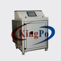
External dimensions: 1060×788×1361mm
Equipment weight: 240Kg
Equipment structure:

Feature:
First charge the battery inside the device, discharge it to the set voltage, and then realize the instantaneous high current test. The discharge time and voltage can be set. After the discharge is completed, it will automatically charge for the next test. The discharge current is recorded during the test, and the system will automatically generate a current-time curve.
Function:
▪ automatic/manual features;
▪ discharge voltage and limit protection time can be set;
▪ waveform curve analysis function;
▪ with overpressure overcurrent protection function;
▪ operation interface (as shown below)


