

Active Member
|
[China]

Address: NO.27,Jinlanling Street,Taigongling Village Dongguan 523829,Guangdong,China
Contact name:Eric

Aolittel Technology Co.,Ltd |
|
|
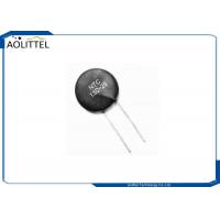
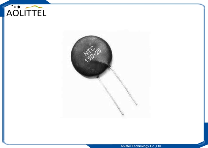
Inrush Current Limiter 1R5 25mm 10A MF72 Power Thermistor NTC 1.5D-25 For Temperature Sensor
Features
RoHS & REACH & Halogen-Free compliant
Diameters covers from 5D to 20D
High Power Rating
Wide resistance range
Cost effective
Applications
Widely used in converter power and switch power
Used for heater, ballast and power circuit protection
Switching power-supply,switch power,UPS power Electronic energy saving lamps electronic ballast and all kinds of electric heater All kinds of RT,display Bulb and other lighting lamps
Description
NTC or Negative Temperature Coefficient Thermistors are typically
used for in-rush current limiting and sensing applications. (As and
NTC thermistor temperature increases its resistance decreses.) For
in-rush applications this attribute is used to reduce current
surges to circuits thereby reducing the probability to tripped
crcuite breakers and blown fuses or damage to motors or filaments.
For sensing applications this attribute allows for the compensation
fo changes in circuit resitances brought about by variations in the
ambient temperature.
Operating Temperature
| Size | Operating Temperature Range |
| φ5mm | -40℃ ~ 155℃ |
| φ7mm/φ9mm/φ11mm | -40℃ ~ 175℃ |
| φ13mm/φ15mm/φ20mm | -40℃ ~ 200℃ |
Electrical Characteristics
| Part No | R25 (Ω) | Max.steady State current (A) | Residual Resistance (Ω) | B25/85 (K) | Themal time Constant (s) | Dissipation factor (mw/℃) | Operating Temperature (℃) |
| 25D-13 | 25 | 2 | 0.625 | 3200 | ≤70 | ≥13 | -40-+200 |
| 30D-13 | 30 | 2 | 0.696 | 3200 | |||
| 33D-13 | 33 | 2 | 0.765 | 3200 | |||
| 47D-13 | 47 | 2 | 1.091 | 3200 | |||
| 50D-13 | 50 | 2 | 1.161 | 3200 | |||
| 60D-13 | 60 | 2 | 1.392 | 3200 | |||
| 80D-13 | 80 | 1.5 | 1.856 | 3200 | |||
| 120D-13 | 120 | 1 | 2.785 | 3200 | |||
| 1.3D-15 | 1.3 | 8 | 0.083 | 2700 | ≤90 | ≥16 | -40-+200 |
| 1.5D-15 | 1.5 | 8 | 0.084 | 2700 | |||
| 2.5D-15 | 2.5 | 7 | 0.135 | 2700 | |||
| 3D-15 | 3 | 7 | 0.136 | 2700 | |||
| 4D-15 | 4 | 6 | 0.199 | 2700 | |||
| 5D-15 | 5 | 6 | 0.127 | 2800 | |||
| 6D-15 | 6 | 5 | 0.188 | 2800 | |||
| 7D-15 | 7 | 5 | 0.191 | 3000 | |||
| 8D-15 | 8 | 5 | 0.201 | 3000 | |||
| 10D-15 | 10 | 5 | 0.209 | 3000 | |||
| 12D-15 | 12 | 4 | 0.267 | 3000 | |||
| 15D-15 | 15 | 4 | 0.305 | 3200 | |||
| 16D-15 | 16 | 4 | 0.306 | 3200 | |||
| 18D-15 | 18 | 4 | 0.338 | 3200 | |||
| 20D-15 | 20 | 4 | 0.347 | 3200 | |||
| 22D-15 | 22 | 4 | 0.381 | 3200 | |||
| 25D-15 | 25 | 3 | 0.433 | 3200 | |||
| 30D-15 | 30 | 3 | 0.519 | 3200 | |||
| 33D-15 | 33 | 3 | 0.571 | 3200 | |||
| 40D-15 | 40 | 3 | 0.587 | 3200 | |||
| 47D-15 | 47 | 3 | 0.690 | 3200 | |||
| 50D-15 | 50 | 3 | 0.734 | 3200 | |||
| 60D-15 | 60 | 3 | 0.881 | 3200 | |||
| 80D-15 | 80 | 2 | 1.175 | 3200 | |||
| 120D-15 | 120 | 1.5 | 1.763 | 3200 | |||
| 0.7D-20 | 0.7 | 11 | 0.105 | 2700 | ≤120 | ≥20 | -40-+200 |
| 1D-20 | 1 | 10 | 0.111 | 2700 | |||
| 1.3D-20 | 1.3 | 9 | 0.131 | 2700 | |||
| 2.2D-20 | 2.2 | 8 | 0.129 | 2800 | |||
| 2.5D-20 | 2.5 | 8 | 0.147 | 2800 | |||
| 3D-20 | 3 | 8 | 0.152 | 2800 | |||
| 5D-20 | 5 | 7 | 0.158 | 3000 |
| Part No | R25 (Ω) | Max.steady State current (A) | Residual Resistance (Ω) | B25/85 (K) | Themal time Constant (s) | Dissipation factor (mw/℃) | Operating Temperature (℃) |
| 6D-20 | 6 | 6 | 0.189 | 3000 | ≤120 | ≥20 | -40-+200 |
| 8D-20 | 8 | 6 | 0.198 | 3000 | |||
| 10D-20 | 10 | 6 | 0.210 | 3000 | |||
| 12D-20 | 12 | 5 | 0.213 | 3200 | |||
| 16D-20 | 16 | 5 | 0.221 | 3200 | |||
| 20D-20 | 20 | 4 | 0.277 | 3200 | |||
| 30D-20 | 30 | 4 | 0.416 | 3200 | |||
| 33D-20 | 33 | 4 | 0.450 | 3200 | |||
| 60D-20 | 60 | 4 | 0.817 | 3200 | |||
| 0.7D-25 | 0.7 | 13 | 0.058 | 2700 | ≤160 | ≥27 | -40-+200 |
| 1D-25 | 1 | 11 | 0.083 | 2700 | |||
| 1.3D-25 | 1.3 | 10 | 0.108 | 2700 | |||
| 1.5D-25 | 1.5 | 10 | 0.125 | 2700 | |||
| 2.5D-25 | 2.5 | 9 | 0.135 | 2800 | |||
| 3D-25 | 3 | 9 | 0.153 | 2800 | |||
| 5D-25 | 5 | 8 | 0.162 | 3000 | |||
| 8D-25 | 8 | 7 | 0.208 | 3000 | |||
| 10D-25 | 10 | 7 | 0.259 | 3300 | |||
| 12D-25 | 12 | 6 | 0.311 | 3300 | |||
| 16D-25 | 16 | 6 | 0.415 | 3300 |
Remark:1.Unless the particular indication,the allowable tolerance of R25 is ±20% ; 2.*is Reference value
Thermistor Terminology-Terms and Concepts Used in Thermistors
To learn about thermistors, a familiarization with the terms frequently used to describe their uses and functions is essential. These are a few of the terms you’re likely to encounter when shopping for thermistors:
Current-time characteristic
At an indicated ambient temperature, this characteristic is the
relationship between the thermistor going through a current and
time when the voltage is introduced or interrupted.
Dissipation Constant
This is the ratio of the change in a thermistor’s power dissipation to the change in its body temperature under specific ambient temperature. This ratio is usually expressed in mill watts per Celsius degree.
Maximum Operating Temperature
This is the thermistor’s maximum body temperature under which it
will continue to operate during a prolonged period without
compromising its stability characteristics. Internal or external
heat or both could generate this temperature, but body temperature
should not go beyond the maximum value indicated.
Maximum Steady-state Current
This term is used in the case of power thermistors. It is the
continuous and stable state current through which the thermistor is
capable of passing. The current could be DC or RMS AC. The maximum
steady-state current for some thermistors is assumed at a maximum
operating ambient temperature of 65 degrees Celsius. It is possible
to have a higher temperature than 65 degrees, and in this case,
thermistors can be designed “to spec.”
NTC
This acronym stands for “negative temperature coefficient.” This is
a type of thermistor that exhibits a decrease in zero-power
resistance when the thermistor’s temperature goes up.
PTC
This acronym stands for “positive temperature coefficient,” and a
PTC thermistor is the opposite of an NTC thermistor in that its
zero-power resistance rises as its body temperature rises.
Stability
Thermistors are usually subjected to a variety of testing
conditions. When they are able to maintain certain characteristics
or qualities after testing methods are applied, they are considered
stable.
Standard Reference Temperature
Twenty-five degrees Celsius (or 77 degrees Fahrenheit) is the
thermistor’s temperature when the zero power resistance is nominal.
This being one of the electrical characteristics most often cited.
Temperature-wattage characteristic
This characteristic refers to the relationship between the
thermistor’s temperature and its steady-state wattage at a
specified ambient temperature.
Thermal Time Constant
When a thermistor changes 63.2% of the difference between its
initial and final body temperature owing to a step function change
in temperature under a zero-power situation, the thermal time
constant is required.
Zero Power Resistance
This refers to a thermistor’s resistance value (dc). It is measured
at a specific temperature when the thermistor’s dissipation of
power is sufficiently low. An additional decrease in power will be
equal to not more than 0.1% in resistance change (or 1/10 of the
tolerance, whichever is smaller).


