Active Member
|
[China]

Address: No.3 Hengshan Road, ETDZ,Yantai,Shandong,China
Contact name:Summer

Yantai Auto Instrument Making Co.,Ltd |
|
|
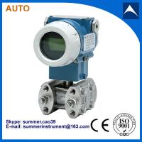
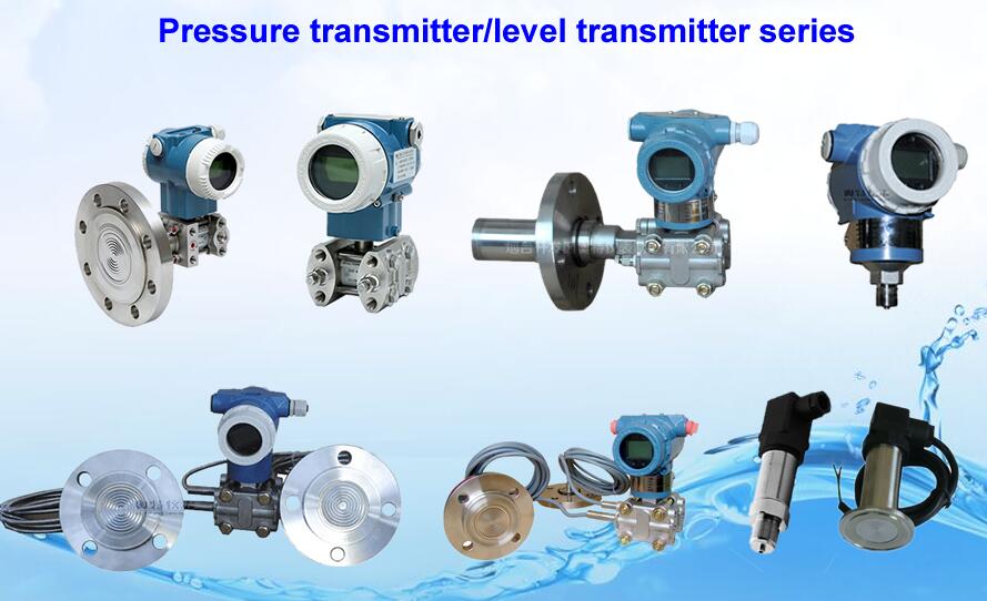
4-20 mA Smart differential pressure level transmitter with HART protocol
Function Parameters:
1. Applicable Object: Liquid, gas, steam
2. Measuring range: 0~0.1KPa to 0~40MPa
3. Output Signal: 4~20mA DC
4. Power Source: 12~45V DC, 24V DC on average
5. Load Characteristic: Depend on power resource. The relation of RL and VS is: RL≤50 (VS-12)
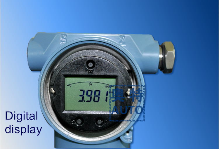
6. Indicating Gauge: Multiple parameters and multiple ways LCD indicate header
7. EX-proof: a. Exd Type ExdllCT6 b. intrinsic safety Type ExidllCT4
8. Range and Zero Point: Outer continually adjustable
9. Positive And Negative Shift: When zero passes positive or negative shift, upper limit and lower limit of
measuring range cannot exceed 100% of upper limit. The maximum positive shift is 500% that of minimum
adjustment range; the maximum negative shift range is 600% that of minimum adjustment range.
10. Temp Range: Working temperature range of amplifier: -29~+93 °c (LT type: -25~+70°c)
11. Filling silicone oil measuring element: -40~+104°C
12. Filling High Temperature Oil to Flange Transmitter : +15~+315°C
13. Common Silicone Oil: -40~+149°C
14. Static Pressure: 4, 10, 25, 32MPa
15. Humidity: relative humidity 0~100%
16. Volume Absorb Quantity: <0.16cm3
Differential Pressure Transmitter MainTechnical Parameters:
Accuracy: | ±0.1%, ±0.075% |
Dead zone: | No (≤0.1%) |
Stability: | Less than the absolute value of basic error of maximum range within 6 months. |
Vibration Effect: | With 200HZ vibration frequency and error that of ±0.05%/g upper limit of measuring range in arbitrary axis |
Power Source Effect: | <0.005%/V output range |
Load Effect: | No load effect under stable power source |
Ording information sheet
Type | Directions |
| |||||||||||
AT1151DP | Differential Pressure Transmitter |
| |||||||||||
Measuring Span | 4 |
|
|
|
| 0~6.2~37.4kPa |
| ||||||
5 |
|
|
|
| 0~31~186.8kPa | ||||||||
6 |
|
|
|
| 0~117~690kPa |
| |||||||
7 |
|
|
|
| 0~345~2068kPa | ||||||||
8 |
|
|
|
| 0~1170~6890kPa | ||||||||
Output signal |
| E |
|
|
| 4~20mA DC |
| ||||||
| S |
|
|
| 4~20mA DC two-wire +HART protocol |
| |||||||
Wetted Parts Material |
|
|
|
|
| Flange/Joint | Exhaust/DrainValve | Diaphragm | Filled liquid |
| |||
|
| 22 |
|
| 316L SS | 316L SS | 316L SS | Silicone oil |
| ||||
|
| 23 |
|
| 316L SS | 316L SS | Hastelloy C | Silicone oil |
| ||||
|
| 24 |
|
| 316L SS | 316L SS | Monel | Silicone oil | |||||
|
| 25 |
|
| 316L SS | 316L SS | Tantalum | Silicone oil | |||||
|
| 56 |
|
| Hastelloy C | Hastelloy C-276 | Hastelloy C-276 | Silicone oil | |||||
Option |
|
|
| M1 |
| Linear Instruction Header (0~100% scale) |
| ||||||
|
|
| M2 |
| Squar e Root Instruction Header(0~100% scale) | ||||||||
|
|
| M3 |
| Four-digit LCD Header(0~100% linear display) |
| |||||||
|
|
| M4 |
| Four-digit LCD Header (can be specifically set ) | ||||||||
|
|
| B1 |
| Tube-type Curved Bracket (Tube ODΦ50~Φ60) |
| |||||||
|
|
| B2 |
| Board- type Curved Bracket | ||||||||
|
|
| B3 |
| Tube-type Straight Bracket (Tube ODΦ50~Φ60) | ||||||||
|
|
| D1 |
| Flange side vent/drain valve at the top |
| |||||||
|
|
| D2 |
| The flange side vent/drain valve at the bottom | ||||||||
|
|
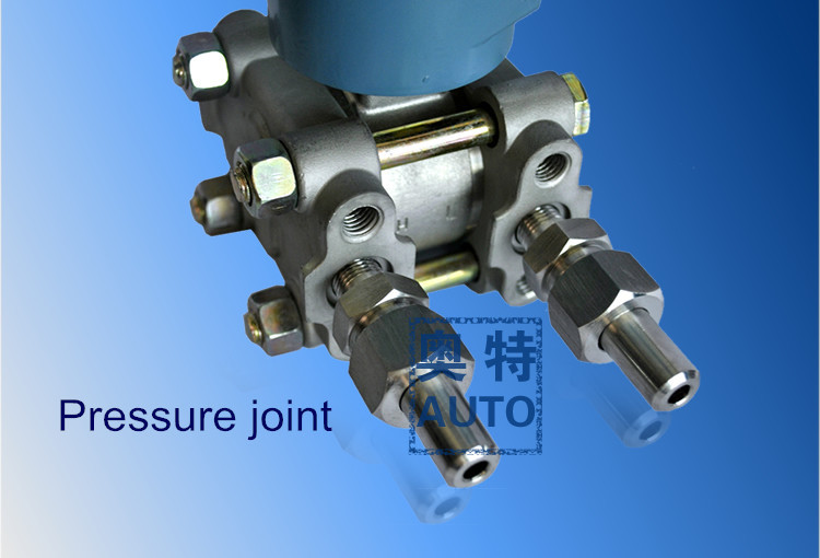
| J |
| D-shaped” Joint with “ M20*1.5” External thread |
| |||||||
|
|
| N |
| “Kidney-shaped” Joint with 1/2-14NPT | ||||||||
|
|
| C12 |
| Cited Pressure Transition Joint with 1/2-14NPT, and Stainless Steel Cited Pressure Pipe Welding in the Rear |
| |||||||
Explosion-proof requirements |
|
|
|
| -- | Standard (no explosion) |
| ||||||
|
|
|
| D | explosion-proof:Exd II BT 5 |
| |||||||
|
|
|
| i | The Ann model:Exia II CT 6 | ||||||||
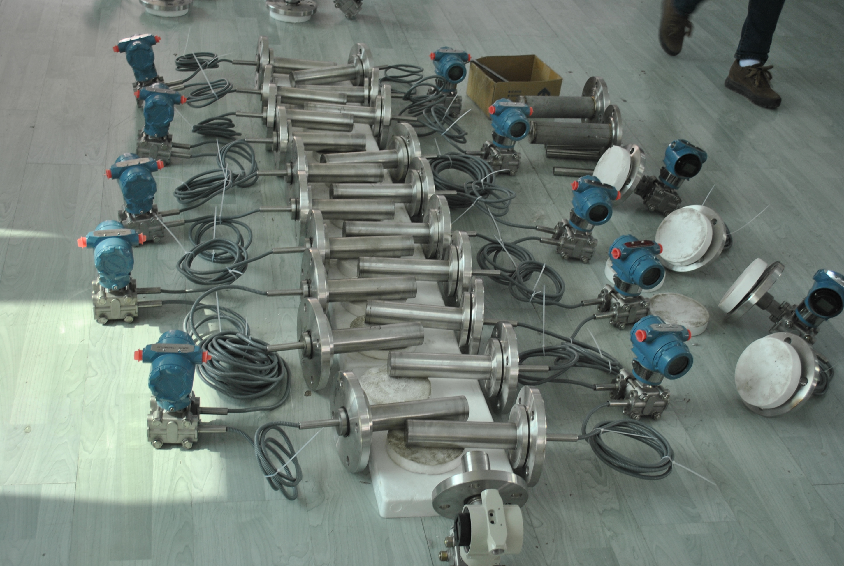
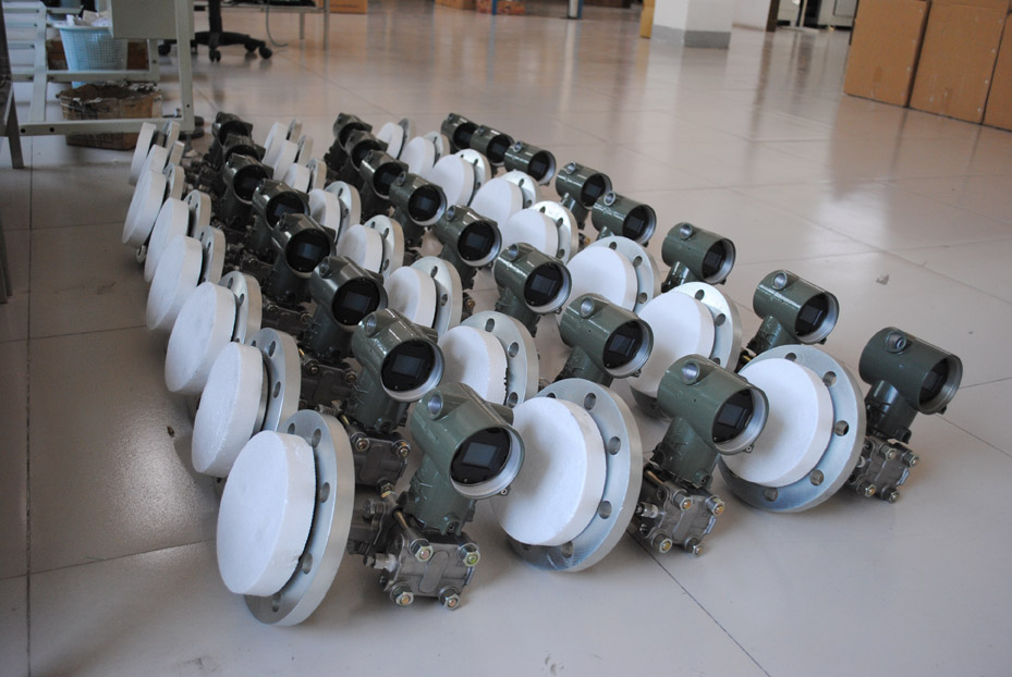
Factory workshop:


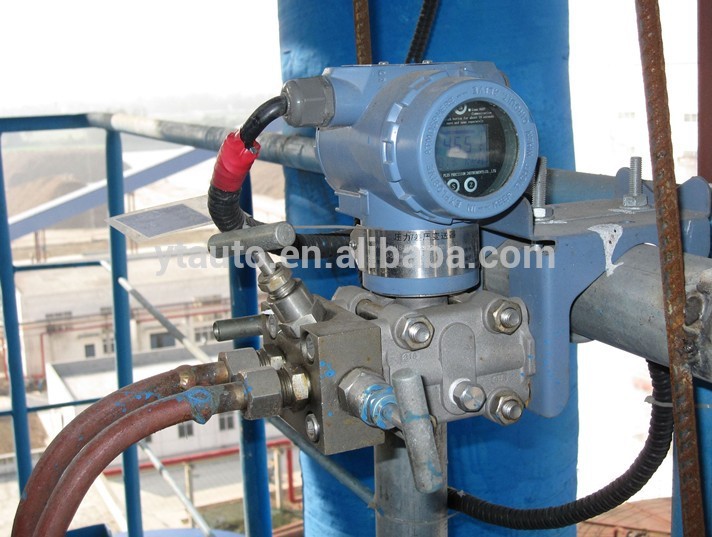
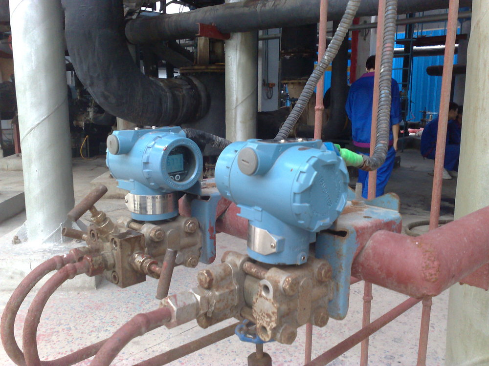
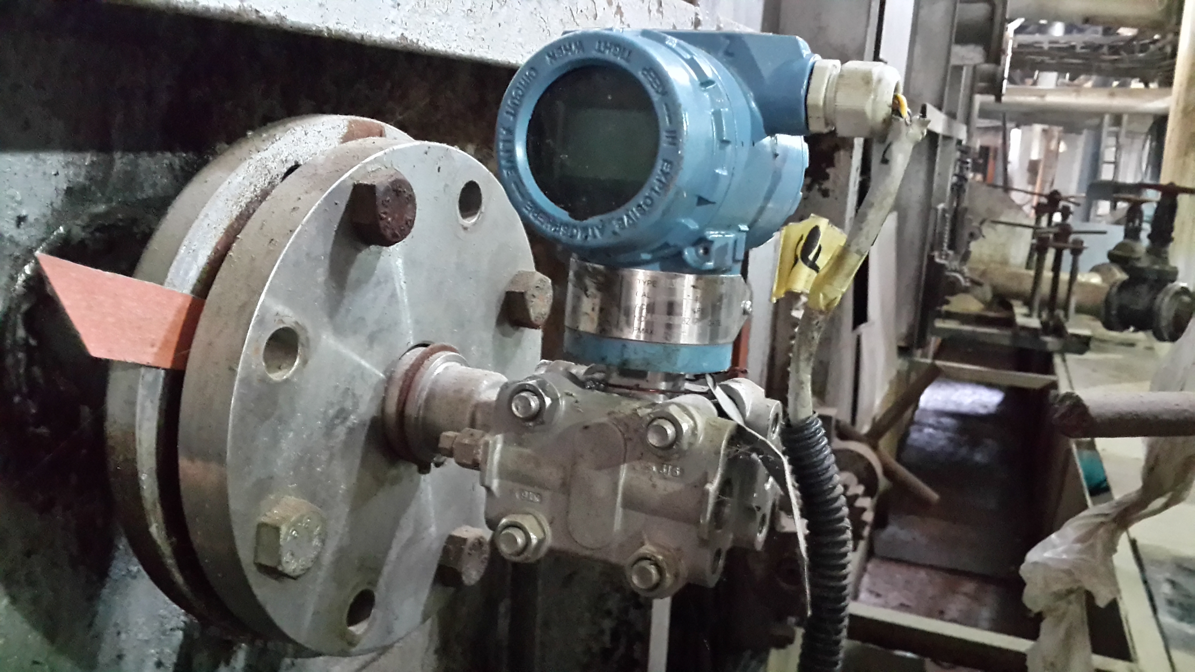
Installation:
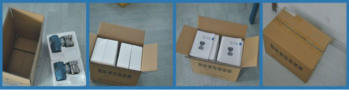
Package:


Contact me: