
|
|
[China]

Trade Verify
Address: Floor 4, Building 8, Xinwei Industrial Zone, Nanshan District, Shenzhen, Guangdong Province, China
Contact name:Charms Zhao

VBE Technology Shenzhen Co., Ltd. |
|
Verified Suppliers
|
|
|
20-3000MHz Waterproof VIP Convoy Bomb Jammer, Vehicle-Mounted IED Jammer
Use Manual - > 20-3000MHz Waterproof VIP Bomb Jammer.pdf
Preface
Note:This Jammer is used for the place where the wireless signal is not allowed.
System Overview
Now, let us introduce this jammer system to you, let you understand the position of all buttons, Component and any other hardware features.

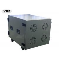
Tag: Main System and Power Supply

Tag: Main System(Front Cover open)

Tag: Power Supply (Front Cover open)

Tag: Power Supply Front View

Tag: Host Front View
Product Features
1. Technical Specification
| Channel | Frequency Range | Output Power(±1dBm) |
| CH1 | 500-1000 MHz | 50 dBm |
| CH2 | 1000-1500 MHz | 50 dBm |
| CH3 | 1500-2000 MHz | 50 dBm |
| CH4 | 2000-2500 MHz | 50 dBm |
| CH5 | 2500-3000 MHz | 50 dBm |
| CH6 | 20-80 MHz | 50 dBm |
| CH7 | 80-200 MHz | 51.3 dBm |
| CH8 | 200-500 MHz | 51.3 dBm |
| CH9 | 851-894 MHz | 51.3 dBm |
| CH10 | 925-960 MHz | 51.3 dBm |
| CH11 | 1805-1990 MHz | 51.3 dBm |
| CH12 | 2110-2170 MHz | 51.3 dBm |
| CH13 | 2400-2500 MHz | 50 dBm |
Power Supply:AC220V Jamming radius: 50-500M depending on the environment signal strength | ||
Power Consumption: 3900W Host Weight :79.5Kg Host Size(L×H×W): 660×480×520 mm Power Supply Weight:49.3Kg Power Supply Size:466×385×420 mm | ||
| Humidity: 30%-95% Working temp: -10 to +55 degree Celsius | ||
Using DDS Jamming technology to make the Frequency setting more precise
Highly Efficiency output power, long jamming radius
Slow start up design of circuit to make the device work stably.
Perfect Self Protection:
Over Heat protection – Thermal protector
Over current protection
High input Voltage and low Voltage protection
VSWR protection: against antenna miss-match including open and short circuit
Waterproof, suitable for using at outdoor.
13pcs RF Output Ports for Connecting Antennas;
2pcs (AC-220V&DC-28V) Input Port;
1 RCU Port for Wire Control Panel.
The jammer full set is made up of host, antennas and remote controller.
Host contains 13 modules. Each module can adjust power, warning standing wave indicator and warning temperature indicator separately .
1. Remote Controller
All the operations are integrated in the remote controller, the user can operate it far from equipment, very convenient.

2. Antenna
Type1:Omni-directional antenna
Gain: 3dBi
| impedance | 50Ω |
| VSWR | ≤1.8 |
| Gain | 3dBi |
| Power | 150W |
| polarization | Vertical |
| intermodulation | <-107dBm |
| Connector | 7/16 or N-K |
| lightning protection | Ground |
| wind barrier | 60(m/s) |
| Diameter | φ40(mm) |
Type2:Directional Board antenna
Interface: N Female
Gain: 13-15dBi
Start to use
Step1 Open the boxes
Open the boxes, retain the boxes that have been unglued for moving or transporting in the future.
Check the opened equipment and accessories to make sure whether they are intact or not. Please contact with your supplier soon if you find our products have any missing parts or damage.
Step2 Connect the electric cable and antennas
1. Coaxial-cable is mainly used in connecting the antenna and jammers, and the antenna must be fixed before connect it.
Notice: The jammer must be started after its antenna has been connected with it, or the jammer will be damaged badly. All costs and consequences which caused by user's this action will bear liability on his own.
2. Please use cables to make the Antenna and Host Port one-to-one connection well.
3. Connect the host and remote control box.
Notice: When you begin to connect the main engine and remote control box, the Red Dot on connecting line's plug must be match with the Red Dot on port's plug, or they cannot be inserted (As shown in the following picture);

4. Please put the 3pin AC INPUT power line which in the power box join up into electric supply through air switch.

Notice: The nominal parameter of air switch must be greater than 10KW/45A, any index of air switch that under this nominal parameter may cause power supply or equipment damage badly, and all costs and consequences which caused by user's this action will bear liability on his own.
Step3 Turn on the jammer
1. Put the air switch to ON position.
2. Open the front cover of power box, and put the ship type switch to "I" position
3. Acquiesce 25% output power while jammer is working, and you can regulate the power size by yourself, and the adjustment method will be illustrated next step.
Step4 Operate Jammer
Our jammers have no any interface about operation or control, all operating is realized through the remote control boxes.
1)The Application Method of Function Key Shortcut.

Tag: The Picture of Function Key Shortcuts
Turn off the red switcher on “off” position
condition of over-wet, over-hot, high voltage and high magnetism.


