2.4G 2400 - 2500MHz Mobile phone Signal Blocker , Wifi Signal
Jammer
Product Preface
- Thank you for using this cell phone signal blocker.
- In order for you to be proficient in the operation of the machine
as soon as possible, we are equipped with a detailed user manual at
random, from which you can obtain information about the product
introduction, usage methods, system settings and security
considerations.
- The wireless signal shield has been strictly certified by the
quality testing Center of Safety and Police Electronic equipment of
the Ministry of Public Security, the quality testing Center of
Electronic products, and the testing Center of electromagnetic
leakage Emission Protection products.
- In writing this manual, we are very careful and careful, and
believe that the information provided in the manual is correct and
reliable, but there will inevitably be mistakes and omissions.
Please include and warmly welcome your correction.
This product is suitable for banning the use of wireless signals!
Product Technical characteristics
- UHF wideband interference technology is adopted.
- High effective power (channel power) and large interference radius.
- Effective segmentation, only interference downlink, will not cause
interference to the base station.
- Imported devices, slow start circuit design can avoid the
mechanical switch fire phenomenon, high integration and stability.
- Perfect self-protection function, when the equipment overheating,
output power, standing wave and other fault alarm, the shield will
automatically close the faulty module, to avoid damage to the
shield.
Product Technical Specifications
| Channel | Working Frequency | Output Frequency(±1dBm) |
| CH1 | 2400 - 2500 MHz | 44.3 dBm |
| Power Supply: AC 220V, when field strength
is -80dBm,Shielding radius is 20 ~ 50M |
Power Consumption: 75W Main motor: 6Kg Size: 225×184×160mm |
| Humidity: 30%-95% Running temperature: -10 to +50 degree |
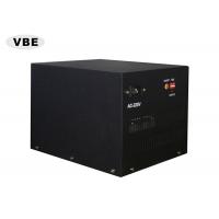
Equipment Accessories

Tag: Control panel diagram
- AC~220V AC in connector
- RF Switch
- Power regulating dial
- Power amplifier alarm status indicator

Tag: Output panel diagram
- RF Output connector(N - type , antenna)
Using Guide
Step 1: opens the box
- Open the box. Keep unpacked boxes ready for future removal or
shipment.
- Check that the open equipment and accessories are in good
condition. If you find any existing defects or damage, please
contact your supplier as soon as possible.
Step 2: connecting cables and antennas
- Coaxial cables are mainly used for the connection of antennas and
shields.
- (Note: do not activate the shield until the antenna and shield are
not well connected, otherwise, the shield will be severely damaged.
All costs and consequences arising therefrom will be borne by the
user himself)
- Cable the antenna to the mainframe port one-to-one.
- Insert the cylindrical end of the 3 pin AC input power cord into
the "AC220V" AC power outlet of the host, and insert the 3 pin head
end into the power supply socket.
Step 3: Start shield
- Press the RF switch and the amplifier starts working while the
orange light in the RF switch is lit.
- The minimum output power of the shield can be adjusted by the dial
disk of the front panel (control panel) of the host machine
according to the actual situation in the field.
Step4: Turn off the shield
- Press the RF switch that has already lit the orange lamp, the
orange light goes out, the power amplifier stops working.
- Disconnect "AC 220V" AC Power Line from Power supply.
- Remove antenna connection cable.