
|
|
[China]

Trade Verify
Address: Room 810, Unit 2, Building 5, Huixing Commercial Center, Dongsheng Road No.1, Zhongshan Dong, Shilong Town Dongguan, GUANGDONG, 523326 CN
Contact name:Anna

Guangdong Uchi Electronics Co.,Ltd |
|
Verified Suppliers
|

|
|
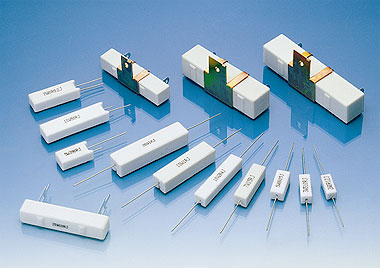
Double End Cement 5W 5 % Resistors 25 Ohm For Power Electronics Circuits
Quick Detail:
1.Small size,resistant to vibration,humidity and heat,good dissipation,low noise and no annual shift in resistance value,low price
2.ZENITHSUN is equipped to design and produce custom components to meet many design and reliability demands. Contact us with your specific needs.
3.Delivery:5-7days
4.Conforms to the ROHS standard and the LEAD-FREE non-lead standard.
Description:
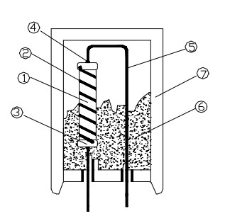
1.cement resistors are made by winding resistance wires around non-alkaline ceramic core,which is added with a layer of heat and humidity resistant and non-corrosive protective material.
2.The wire wound resistor is then placed in a square ceramic package sealed with special nonflammable heat-resistant cement.
3.For high resistance value,wires are replaced by metal oxide films.
Applications:
Complete insulation suitable for printed circuit boards,Power supplies ,Voltage dividers ,Motor controllers ,Automotive applications ,Power electronics circuits.
Specifications:
| 1. General
1.1 Scope This specification is available for Cement Resistor manufactured by,it accords with RoHS test of Environment related substance requirement.
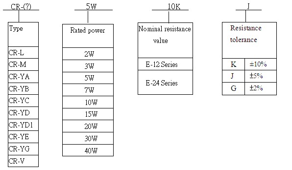
1.2 Type designation (example)
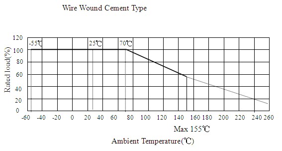
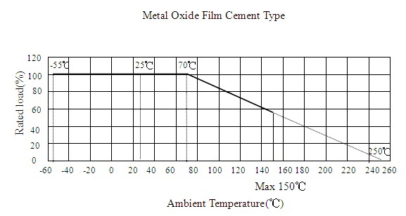
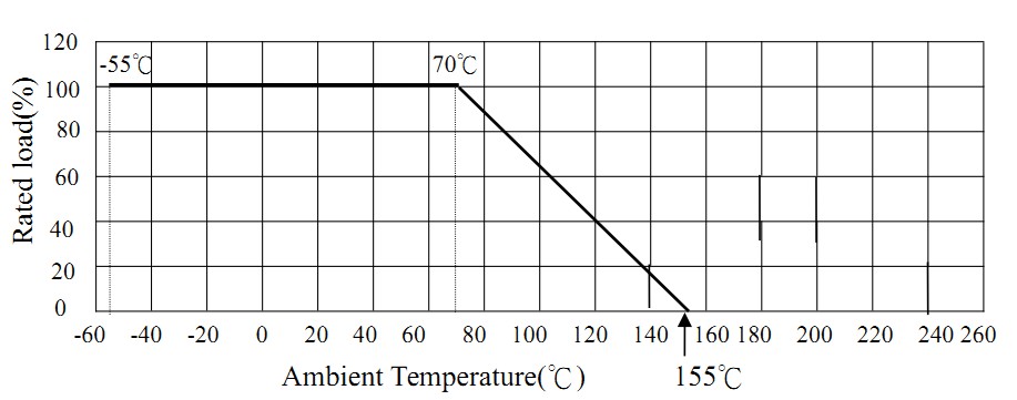
The type designation shall be in the following form and as specified. 1.3 Rated power Rated power is maximum power which can be continuously loaded at specified ambient temperature 70℃,as Table-1;however when the ambient temperature exceeds 70℃,rated power should be determined from the derating curve of Fig.1.
| |||||||||||||||||||||||||||||||||||||||||||||||||||||||
| Table-1
Figure 1 Power derating curve Rated ambient temperature: 1W~10W 70℃ 15W or more 25℃
Rated ambient temperature: 1W~10W 70℃ 15W or more 25℃
1.4 Rated voltage
The rated voltage shall be the D.C. or A.C.(R.M.S. at power frequency) voltage which corresponds the rated power and the value of which is calculated from the formula below.
| |||||||||||||||||||||||||||||||||||||||||||||||||||||||
| E=√(P×R) Where E: Rated voltage(V) P: Rated power(W) R: Nominal resistance(Ω) Operating Temperature Range:-55℃~+250℃
2. Construction
2.1 External dimensions
The dimensions shall be satisfied with [5. External dimensions].
2.2 Structure diagram
The construction of cement resistor shall be as follows:
| |||||||||||||||||||||||||||||||||||||||||||||||||||||||
| 3. Characteristics Table-2
| |||||||||||||||||||||||||||||||||||||||||||||||||||||||
|
4. Indication
(1) Rated Power
(2) Resistance
(3) Tolerance
Sample
| 5W 100Ω J |
5. External dimensions
5.1 CR-L type
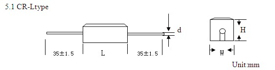
| Watt | Dimensions(mm) | Resistance Range(Ω) | ||||
| L | W | H | Φd±0.05 | Wire Wound | Metal Oxide Film | |
| 1W | 14±1.0 | 6.5±1.0 | 6.5±1.0 | 0.50 | 0.1Ω~22Ω | 25Ω~56KΩ |
| 2W | 18±1.0 | 7.0±1.0 | 7.0±1.0 | 0.50 | 0.1Ω~22Ω | 25Ω~56KΩ |
| 3W | 22±1.0 | 8.0±1.0 | 8.0±1.0 | 0.68 | 0.1Ω~47Ω | 50Ω~100KΩ |
| 5W | 22±1.0 | 9.5±1.0 | 9.5±1.0 | 0.68 | 0.1Ω~47Ω | 50Ω~100KΩ |
| 7W | 35±1.5 | 9.5±1.5 | 9.5±1.5 | 0.68 | 0.5Ω~330Ω | 450Ω~100KΩ |
| 10W | 48±1.5 | 9.5±1.5 | 9.5±1.5 | 0.68 | 0.5Ω~450Ω | 470Ω~100KΩ |
| 15W | 48±1.5 | 13±1.5 | 13±1.5 | 0.68 | 1Ω~500Ω | 510Ω~100KΩ |
| 20W | 63±1.5 | 13±1.5 | 13±1.5 | 0.68 | 1Ω~600Ω | 620Ω~100KΩ |
| 30W | 75±2.0 | 19±2.0 | 17±2.0 | 0.68 | 1Ω~600Ω | 620Ω~100KΩ |
| 40W | 89±2.0 | 19±2.0 | 19±2.0 | 0.68 | 1Ω~600Ω | 620Ω~100KΩ |
5.2 CR-M type
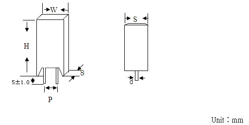
| Watt | W±1.0 | S±1.0 | H±1.5 | Φd±0.05 | P±1.0 | Resistance Range(Ω) | |
| Wire Wound | Metal Oxide Film | ||||||
| 2W | 11.5 | 7.5 | 20.5 | 0.70 | 4.5 | 0.1Ω~47Ω | 50Ω~100KΩ |
| 3W | 12 | 8.5 | 25 | 0.70 | 4.5 | 0.1Ω~47Ω | 50Ω~100KΩ |
| 5W | 13 | 9.5 | 25 | 0.75 | 4.5 | 0.1Ω~47Ω | 50Ω~100KΩ |
| 7W | 13 | 9.5 | 38 | 0.70 | 4.5 | 0.5Ω~330Ω | 450Ω~100KΩ |
| 10W | 13 | 9.5 | 52 | 0.70 | 4.5 | 0.5Ω~450Ω | 470Ω~100KΩ |
| 10W | 16 | 11.5 | 36 | 0.70 | 4.5 | 0.5Ω~450Ω | 470Ω~100KΩ |
| 15W | 13 | 10 | 50 | 0.70 | 4.5 | 0.5Ω~450Ω | 470Ω~100KΩ |
| 20WS | 13 | 10 | 50 | 0.70 | 4.5 | 0.5Ω~450Ω | 470Ω~100KΩ |
| 20W | 20 | 10 | 40 | 0.70 | 7.0 | 0.5Ω~450Ω | 470Ω~100KΩ |
5.3 CR-YB type
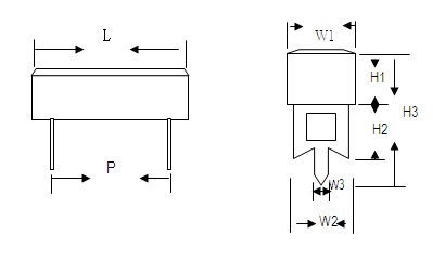
Unit:mm
| Watt | Dimensions(mm) | Resistance Range(Ω) | |||||||
| L | P±1.5 | W1±1.2 | W2±0.2 | W3±0.2 | H1±1.2 | H2±0.2 | H3±1.5 | ||
| 15 | 48±1.5 | 32.5 | 12.5 | 10 | 2.7 | 12.5 | 15 | 36 | 1.0-820 |
| 20 | 63±2 | 44 | 12.5 | 10 | 2.7 | 12.5 | 15 | 36 | 1.0-1K |
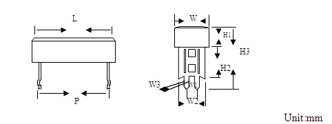
5.4 CR-YD type
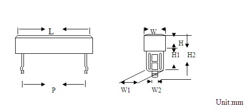
| Watt | Dimensions(mm) | Resistance Range(Ω) | |||||||
| L | P±1.5 | W±1.0 | W1±0.2 | W2±0.2 | H±0.2 | H1±0.2 | H2±1.5 | ||
| 3 | 24±1.0 | 12 | 9.5 | 7.5 | 1.6 | 9.5 | 25 | 39 | 0.5-150 |
| 5 | 27±1.0 | 15 | 9.5 | 7.5 | 1.6 | 9.5 | 25 | 39 | 0.5-220 |
| 7 | 35±1.5 | 22.5 | 9.5 | 7.5 | 1.6 | 9.5 | 25 | 39 | 1-470 |
| 10 | 48±1.5 | 34 | 9.5 | 7.5 | 1.6 | 9.5 | 25 | 39 | 1-680 |
| 15 | 48±1.5 | 32.5 | 12.5 | 10 | 3 | 12.5 | 30 | 47.5 | 1-820 |
| 20 | 63±2.0 | 44 | 12.5 | 10 | 3 | 12.5 | 30 | 47.5 | 1-1K |
5.5 CR-YA type
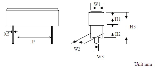
| Watt | Dimensions(mm) | Resistance Range(Ω) | |||||||
| L | P±1.5 | W1±1.0 | W2±0.2 | W3±0.2 | H1±0.2 | H2±0.2 | H3±0.2 | ||
| 3 | 24±1.0 | 12 | 9.5 | 5.3 | 0.9 | 9.5 | 10 | 25.5 | 0.5-150 |
| 5 | 27±1.0 | 15 | 9.5 | 5.3 | 0.9 | 9.5 | 10 | 25.5 | 0.5-220 |
| 7 | 35±1.5 | 22.5 | 9.5 | 5.3 | 0.9 | 9.5 | 10 | 25.5 | 1-470 |
| 10 | 48±1.5 | 34 | 9.5 | 5.3 | 0.9 | 9.5 | 10 | 25.5 | 1-680 |
5.6 CR-YC type
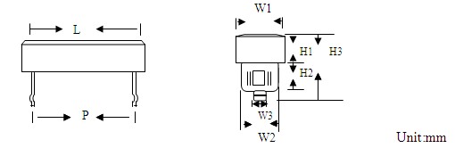
| Watt | Dimensions(mm) | Resistance Range(Ω) | |||||||
| L | P±1.5 | W1±1.0 | W2±0.2 | W3±0.2 | H1±1 | H2±0.5 | H3±1.5 | ||
| 3 | 24±1.0 | 12 | 9.5 | 7.3 | 1.6 | 9.5 | 10 | 25 | 0.5-150 |
| 5 | 27±1.0 | 15 | 9.5 | 7.3 | 1.6 | 9.5 | 10 | 25 | 0.5-220 |
| 7 | 35±1.5 | 22.5 | 9.5 | 7.3 | 1.6 | 9.5 | 10 | 25 | 1-470 |
| 10 | 48±1.5 | 34 | 9.5 | 7.3 | 1.6 | 9.5 | 10 | 25 | 1-680 |
5.7 CR-YE type
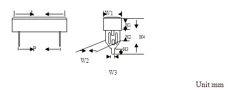
| Watt | Dimensions(mm) | Resistance Range(Ω) | ||||||||
| L | P±1.5 | W1±1.0 | W2±0.2 | W3±0.2 | H1±0.2 | H2±0.2 | H3±1.5 | H4±1.5 | ||
| 3 | 24±1.0 | 12 | 9.5 | 7.4 | 3 | 9.5 | 7.5 | 4.5 | 30.4 | 0.5-150 |
| 5 | 27±1.0 | 15 | 9.5 | 7.4 | 3 | 9.5 | 7.5 | 4.5 | 30.4 | 0.5-220 |
| 7 | 35±1.5 | 22.5 | 9.5 | 7.4 | 3 | 9.5 | 7.5 | 4.5 | 30.4 | 1-470 |
| 10 | 48±1.5 | 34 | 9.5 | 7.4 | 3 | 9.5 | 7.5 | 4.5 | 30.4 | 1-680 |
5.8 CR-YD1 type
| Watt | Dimensions(mm) | Resistance Range(Ω) | ||||||||
| L | P±1.5 | W±1 | W2 | W3 | W1 | H1 | H2 | H3 | ||
| 15 | 48±1.5 | 22 | 12.5 | 10 | 1.5 | 5 | 12.5 | 30 | 47.5 | 10-820 |
| 20 | 63±2.0 | 44 | 12.5 | 10 | 1.5 | 5 | 12.5 | 30 | 47.5 | 1.0-1K |
5.9 CR-V type
| Watt | Dimensions(mm) | Resistance Range(Ω) | ||||||||
| L1 | L2±0.2 | L3±0.2 | H1±0.2 | H2±0.2 | H3±1.0 | W1±1.0 | W2±0.2 | W3±0.5 | ||
| 5 | 31±1.0 | 5 | 4 | 1.5 | 11 | 9.5 | 9.5 | 1.5 | 11.5 | 0.5-220 |
| 7 | 49±1.5 | 10 | 4 | 1.5 | 11 | 9.5 | 9.5 | 1.5 | 11.5 | 1-470 |
| 10 | 62.5±2 | 10 | 4 | 1.5 | 11 | 9.5 | 9.5 | 1.5 | 11.5 | 1-680 |
| 15 | 63.5±2 | 10 | 4.5 | 2.5 | 14.5 | 13 | 13 | 2.5 | 15.5 | 1-820 |
| 20 | 75±2 | 10 | 4.5 | 2.5 | 17.5 | 13 | 13 | 2.5 | 15.5 | 1-1K |
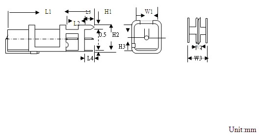
5.10 CR-H type
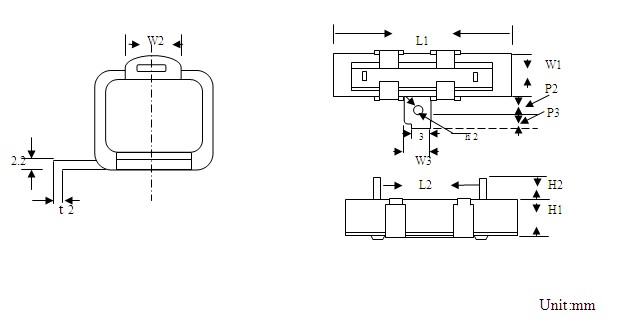
| Watt | Dimensions(mm) | Resistance Range(Ω) | ||||||||||
| L1 | L2±1.0 | W3±0.2 | P2 | P3 | t2 | h2 | W1 | W2 | H1 | H2 | ||
| 10 | 48±1.5 | 23 | 12 | 6 | 8 | 0.6 | 4 | 9.5±1.0 | 5 | 9.5±1.0 | 6±1.5 | 1-680 |
| 15 | 48±1.5 | 23 | 12 | 7 | 8 | 0.8 | 4 | 12.5±1.2 | 6 | 12.5±1.2 | 7.5±2.0 | 10-820 |
| 20 | 63±2.0 | 23 | 12 | 7 | 10 | 0.8 | 4 | 12.5±1.2 | 6 | 12.5±1.2 | 7.5±2.0 | 1-1K |
| 30 | 75±2.5 | 56 | 18 | 9 | 10 | 0.8 | 4.2 | 19±1.5 | 7.5 | 19±1.5 | 10±2.0 | 1-1K |
| 40 | 88±2.5 | 68 | 18 | 9 | 10 | 0.8 | 4.2 | 19±1.5 | 7.5 | 19±1.5 | 10±2.0 | 1-1K |
Competitive Advantage:
1. Factory supply directly
2. Completed certificates such as UL,VDE,SGS,etc and high quality available
3. Quick delivery
4. Best after-sales services
5. OEM & ODM available


 R1-R0/R0(T1-T0)×106(PPM/℃)


