Installation
Double Disc Check Valves, also called wafer check valves are
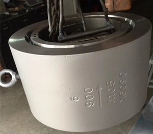
designed to be installed between ANSI 150, 300, 600,900 or 1500LB
flanges. These valves should not beinstalled between flanges that
contain defects.
Prior to installation, the wafer ends and mating flanges should be
inspected to ensure gasket surfaces are free of defects. The piping
system must also be checked for proper alignment.
Double Disc Check Valves should never be utilized to realign an
existing piping system. Our Dual Plate Check Valves are designed
for steady flow conditions and can be installed in either
horizontal orvertical (flow upwards) pipelines.
1)Horizontal Installation
The valve rib must be installed perpendicular to the flow. This is
shown in the diagram below. The eyebolt is locateddirectly above
the valve rib and can be used to correctly position the valve.
2)Vertical Installation
Check Valves must be installed with the flow direction upward. In
this position, the outlet will be above the inlet. It is also
necessary to orientate the valve rib such that there is equal
loading on the dual plates. This is illustrated in the diagram
below. Additional pressure drop should be expected due to the
weight of the discs.
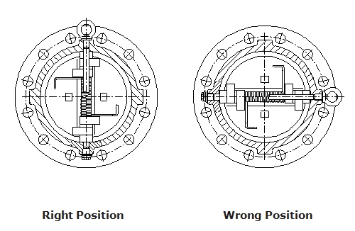
When positioning the Check Valve, ensure that the arrow on the body
of the valve points in the direction of the flow.
During installation, it is important to support and align the check
valve and the adjacent piping. Install a standard, ANSI flange
gasket between valve and flange, on both sides. Install lubricated
flange bolts and hand tighten. Flange bolts should then be
tightened using a star or crisscross pattern to evenly load the
bolts.
For efficient function and improved service life, recognized piping
standards stipulate placing Check Valves 5 to 10 pipe diameters
from any turbulence producing devices.Dual Plate Check Valves are
designed for steady flow conditions and are not recommended for low
flow,reciprocating flow, pulsating flow, or parallel pumping
station. Dual Plate Check Valves are designed to operate properly
for flow rates between 5 ft./sec to 10 ft./sec. It is not
recommended to exceed the maximum flow rate of 10 ft./sec or the
minimum flow rate of 5 ft.
Installation is complete when the wafer ends are flush against the
mating flanges and no gaps are present.
Operation
Dual Plate Check Valves are designed to automatically prevent
backflow in systems where it is desirable to permit flow in one
direction and prevent flow in the opposite direction. When the pump
starts and the downstream flow creates the required pressure drop
in the forward direction, the Dual Plates will automatically open.
When the pump stops and the flow ceases, the torsion of the spring
will automatically close the Dual Plates prior to flow reversal.
This creates a positive shutoff against flow reversal and
eliminates system surges and water hammer. 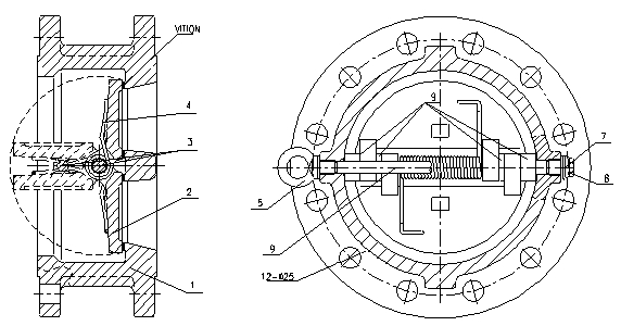
| Item No. | Part No. | Material |
|---|
| 1 | Body | A216 WCB |
| 2 | Disc | WCB+ENP |
| 3 | Stop Pin | A276 420 |
| 4 | Spring | Inconnel 625 |
| 5 | Lifting Eye | A29 1025 |
| 6 | Gasket | SS 304 |
| 7 | Gasket | SS304+Graphite |
| 8 | Retainer | A193 B7 |
| 9 | Shaft | 13 Cr |
Maintenance
Our Dual Plate Check Valves are designed for continuous, problem
free service and do not require regularly scheduled maintenance.
Leakage
Periodic inspections for leakage should be performed. If leakage is
present, check the flange gasket and flange bolttorque. In some
situations, it may be necessary to isolate the Check Valve by
shutting off upstream and downstream valves. Then remove the Check
Valve and inspect the seating surfaces for damage. Dual Plate Check
Valves contain Elastomer seats which are vulcanized and bonded to
the body castings.They are not adjustable or replaceable in the
field.When removing the Check Valve for inspection, please follow
the removal instructions presented in this manual. Always relieve
pressure from both sides of the Check Valve before inspection.
Vibration Verify that flow rate is within acceptable ranges
Additionally, verify that the Check Valve is 5 to 10 pipe diameters
from any turbulence producing devices Slamming. Remove Check Valve
from piping system and inspect the spring. Verify that the spring
is providing the proper tension. Restricted Flow if flow is halted
at the Check Valve, verify that the flow direction arrow is
pointing in the direction of the flow.
Valve Removal
To remove the Check Valve from the pipeline, first isolate the
Check Valve and drain the system as much as possible.
Relieve pressure from both sides of the Check Valve by venting the
line.
Loosen the outlet flange bolts first then theinlet flange bolts to
decompress gasket seals. Attach required lifting equipment and
remove the Check Valve from the pipeline.


, 150# (PN 16), Standard API 594.China Dual Plate Check Valve Ma")
, 150# (PN 16), Standard API 594.China Dual Plate Check Valve Ma")
, 150# (PN 16), Standard API 594.China Dual Plate Check Valve Ma")
, 150# (PN 16), Standard API 594.China Dual Plate Check Valve Ma")
, 150# (PN 16), Standard API 594.China Dual Plate Check Valve Ma")