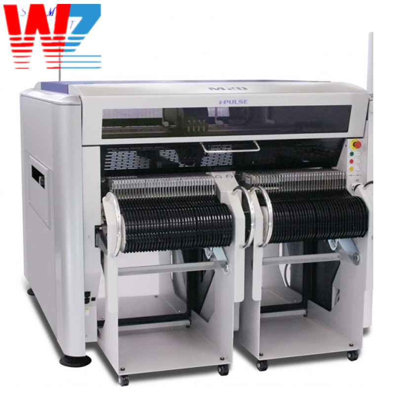
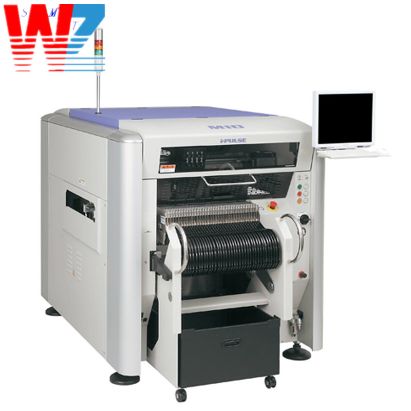
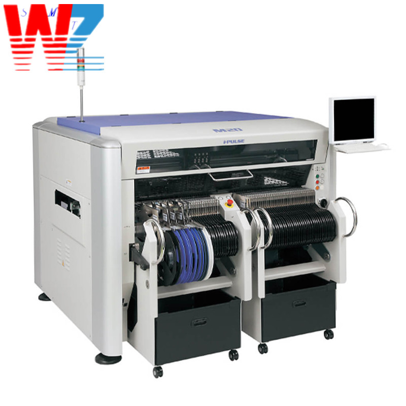
Yamaha iPulse M10 , M20 , M3 high speed smt pick and place machine
The Yamaha M10 pick and place machine is a state-of-the-art
equipment used in the electronics manufacturing industry for
high-precision placement of electronic components onto printed
circuit boards (PCBs). It offers advanced functionality,
versatility, and efficiency to streamline the assembly process.
Functionality:
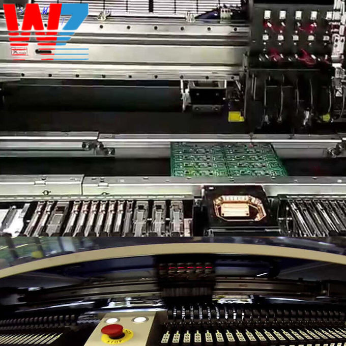
1. Component Placement: The Yamaha M10 pick and place machine is
designed to accurately pick electronic components from the
component feeders and place them onto the designated locations on
the PCBs. It utilizes advanced vision systems, robotic arms, and
placement heads to achieve precise and reliable component
placement.
2. High-Speed Operation: The machine is capable of high-speed
operation, ensuring rapid placement of components onto the PCBs. It
features a high-speed head that can handle a large number of
components per hour, resulting in improved production efficiency
and reduced cycle times.
3. Component Compatibility: The Yamaha M10 pick and place machine
supports a wide range of electronic components, including surface
mount devices (SMDs), through-hole components, and odd-shaped
components. It can handle various package types, such as resistors,
capacitors, integrated circuits (ICs), connectors, and more.
4. Multi-Function Heads: The machine is equipped with
multi-function heads that can handle different types of components.
These heads have interchangeable nozzles to accommodate various
component sizes and shapes. They can also perform additional
functions, such as testing, dispensing, and inspection, further
enhancing the machine's versatility.
5. Vision Systems: The machine features advanced vision systems
that enable precise component alignment, verification, and
correction. The vision systems can detect and correct for any
variations in component orientation, ensuring accurate placement
even for components with irregular shapes or variations in
presentation.
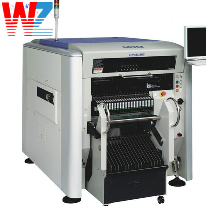
6. Intelligent Feeders: The Yamaha M10 pick and place machine
utilizes intelligent feeders that provide efficient component
supply. These feeders can hold multiple component reels or trays
and automatically feed the components to the pick and place heads.
They are equipped with sensors to monitor component availability
and prevent errors caused by empty feeders.
| | Yamaha I-pulse M10 |
| Board size(with buffer unused) | Min. L50 x W30mm to Max. L980 x W510mm *1 |
| Board size(with input or output buffer used) | Min. L50 x W30mm to Max. L420 x W510mm |
| Board size(with input and output buffers used) | Min. L50 x W30mm to Max. L330 x W510mm |
| Board thickness | 0.4 - 4.8mm |
| Board flow direction | Left to right (Standard) |
| Board transfer speed | Max 900mm/sec |
| Placement speed (4 heads + 1 theta) Opt. Cond. | 0.15sec/CHIP (24,000CPH) |
| Placement speed (4 heads + 4 theta) Opt. Cond. | 0.15sec/CHIP (24,000CPH) |
| Placement speed (6 heads + 2 theta) Opt. Cond. | 0.12sec/CHIP (30,000CPH)*2 |
| Placement speed (4 heads + 1 theta) IPC9850 | 19,000CPH |
| Placement speed (4 heads + 4 theta) IPC9850 | 19,000CPH |
| Placement speed (6 heads + 2 theta) IPC9850 | 23,000CPH*2 |
| Placement accuracy A (?+3?) | CHIP +/-0.040mm |
| Placement accuracy B (?+3?) | IC +/-0.025mm |
| Placement angle | +/-180 degrees |
| Z axis control | AC servo motor |
| Theta axis control | AC servo motor |
| Component height | Max 30mm*3 (Pre-placed components: max 25mm) |
| Applicable components | 0402 to 120x90mm, BGA, CSP, connector, etc. |
| Component package | 8 - 56mm tape (F1/F2 Feeders), 8 - 88mm tape (F3 Electric Feeders),
stick, tray |
| Drawback check | Vacuum check and vision check |
| Screen language | English, Chinese, Korean, Japanese |
| Board positioning | Board grip unit, front reference, auto conveyor width adjustment |
| Component types | Max 72 types (8mm tape), 36 lanes x 2 |
| Transfer height | 900 +/- 20mm |
| Machine dimensions, weight | L1250xD1750xH1420mm, Approx. 1,150kg |
| Power | 3-phase 200/208/220/240/380/400/416/440V +/-10%
(Transformer included), 50/60Hz |
| Max consumption, capacity | 1.1kW, 5.5kVA |
| Air pressure, consumption | 0.45Mpa, 50(4 heads) or 75(6 heads) L/min A.N.R. |
Usage Instructions:
1. Setup: Ensure that the Yamaha M10 pick and place machine is
properly installed and connected to the power supply. Set up the
component feeders and align them with the machine's feeder slots.
Verify that the vision systems are properly calibrated.
2. Programming: Create or import the assembly program for the
specific PCB layout and component placement. Use the machine's
software interface to define component positions, pick-up points,
and placement coordinates. Adjust programming parameters such as
component height, vision system settings, and placement accuracy as
needed.
3. Feeder Loading: Load the component reels or trays onto the
intelligent feeders. Ensure that the components are properly loaded
and aligned within the feeders. Configure the machine's control
system to recognize and manage the loaded feeders.
4. PCB Loading: Prepare the PCBs for placement by ensuring they are
clean, properly aligned, and secured on the machine's worktable or
conveyor. Ensure that fiducial marks on the PCB are visible for the
vision system's alignment.
5. Machine Calibration: Perform necessary calibration procedures to
ensure precise component placement. This may include calibrating
the vision system, verifying the accuracy of the pick and place
heads, and adjusting any mechanical or alignment settings.
6. Start Operation: Start the Yamaha M10 pick and place machine and
initiate the assembly program. 6. Monitor the machine's operation
to ensure that components are picked accurately from the feeders
and placed precisely onto the PCBs. Monitor the vision system's
alignment and correction processes to ensure proper component
orientation.
7. Maintenance: Regularly inspect the machine for signs of wear,
damage, or malfunction. Keep the machine clean and free from debris
that may affect its performance. Follow the manufacturer's
maintenance guidelines for any required lubrication, cleaning, or
component replacement.
The Yamaha M10 pick and place machine provides advanced
functionality for high-precision component placement onto PCBs. By
following the proper usage instructions, it enables efficient and
accurate assembly, contributing to improved productivity and
quality in the electronics manufacturing process.