Active Member
|
[China]

Contact name:Albert

Shenzhen Greetwin Technology Co.,Limited |
|
|
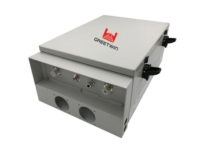
Cable Access Fiber Optical signal repeater for mobile phone , GSM 900MHz
Fiber Optical signal repeater Description:
Greetwin Fiber Optic Repeaters system is designed to solve problems of weak mobile signal, which is much cheaper than setup a new Base Station (BTS). Main operation of RF Repeaters system: For the down link, signals from BTS is fed to Master Unit(MU), the MU then convert RF signal to laser signal then feed to fiber to transmit to Remote Unit(RU). RU then convert laser signal to RF signal, and use Power Amplifier to amplify to high power to IBS or coverage antenna. For the up link, Is a reverse process, signals from user mobile is fed to MU’s MS port. Via duplexer, the signal is amplified by low noise amplifier to improve signal strength. Then the signals is fed to RF fiber optical module then converted to laser signals, then the laser signal is transmit to MU, the laser signal from RU is convert to RF signal by RF optical transceiver. Then the RF signals are amplified to more strength signals fed to BTS.
The Fiber Optic Repeater (FOR) is designed to solve problems of
weak mobile signal in such place: Far away from the BTS (Base
Transceiver Station) and has fiber optic cable network underground.
The whole FOR system consists of two parts: Donor Unit and Remote
Unit. They transparently convey and amplify the wireless signal
between the BTS (Base Transceiver Station) and mobiles via fiber
optic cables.
The Donor unit captures the BTS signal via a direct coupler closed
to the BTS (or via open air RF transmission through the Donor
Antenna), then converts it into optic signal and transmits the
amplified signal to the Remote Unit via fiber optic cables. The
Remote Unit will reconvert the optic signal into RF signal and
provide the signal to the areas where network coverage is
inadequate. And the mobile signal is also amplified and
retransmitted to the BTS via the opposite direction.
As per the method of receiving BTS signal by the Donor Unit, two
types of FOR are available:
Cable-Access FOR: To receive BTS signal via a direct coupler closed to the BTS
(recommended);
Wireless-Access FOR: To receive BTS signal via a Donor Antenna (applicable when no
fiber optic cable connecting to the BTS); Can be sorted into 2
sub-categories: Band-Selective and Channel-Selective.
Fiber Optical signal repeater Features:
1. High level, high availability, convenient for maintain;
2. Internal adopt intelligent monitoring, is convenient to locate the faults for maintain;
3. Low power consumption, excellent heat dissipation;
4. High linearity PA, high system gain;
5. Local and remote monitoring (optional) with automatic fault alarm &remote control;
6. Compact size, flexible for installation and relocation;
7. Weatherproof design for all-weather installation;
8. One MOU can support Max 8 ROUs, Save cost and ease installation.
The FOR is mainly applicable to such case:
· Underground fiber optic cable network already exists beneath the
area to be covered;
· There is huge obstructive terrain between the BTS and the area to
be covered;
· The distance between the BTS and the area to be covered is 20 km
around.
In comparison with RFR (RF repeater) and FSR (frequency shift
repeater), the FOR has the following benefits and disadvantages:
Pro:
No more self-oscillation and easy to choose installation location;
For Cable-Access type, pure BTS signal picked up by the Donor Unit
will greatly reduce the signal noise;
The Remote Unit can be installed out of the BTS coverage;
A full 360-degree coverage can be realized;
No need to occupy frequency resource as the link frequency.
Con:
· The total cost of equipment is higher;
· A fiber optical connection between the Donor Unit and Remote Unit
is required.
Application:
To expand signal coverage or fill signal blind area where signal is
weak or unavailable.
· Outdoor: Airports, tourism regions, golf courses, tunnels,
factories, mining districts, villages, highways
· Indoor: Hotels, exhibition centers, basements, shopping malls,
offices, parking lots.
Data Sheet:
Master Unit(MU) Technical Specification:
| Items | Testing Condition | Technical Specification | Memo | |||
| Downlink | Uplink | |||||
| Frequency Range | Working in-band | 890-915MHz | 935-960MHz | |||
| Bandwidth | Working in-band | 25MHz | ||||
| Output Power | Working in-band | - | 0dBm | |||
| Max RF Input level | Working in-band | -30dBm | - | |||
| Min RF Input level | Working in-band | -110dBm | - | |||
| Max RF input without damage | Working in-band | 10dBm | - | |||
| Noise Figure | Working in-band | ≤5dB | - | |||
| VSWR | Working in-band | ≤1.5 | ||||
| Time Delay | Working in-band | ≤12.0μs | ||||
| Spurious Emission | 9kHz-1GHz | BW:30KHz | ≤-36 | ≤-36 | ||
| 1GHz-12.75GHz | BW:30KHz | ≤-30 | ≤-30 | |||
| Connector | N-Female | |||||
| Optical Specifications | ||||||
| Optical Output Power | -8dBm±2dB | - | ||||
| Optical Max Input power | +4dBm | |||||
| Optical Min Input power | +0dBm | |||||
| Optical Input damage level | +10dBm | |||||
| Optical length | DL: 1310nm, UL: 1550nm | |||||
| Optical Loss | ≤10dB /Includes the loss of the optical splitter | |||||
| Optical Connector | FC/APC(WDM, one core) | |||||
| Nos Of Optical Ports | 1-4 | |||||
| Power Supply and Mechanical Specifications | ||||||
| Power Supply | AC220V±60V,45~55Hz | |||||
| Dimension | 530mm*310mm*190mm | |||||
| Weight | 19kg | |||||
| Max. Power Consumption | 150W | |||||
| Operating Temperature | -5~+45℃ | |||||
| Operating Humidity | ≤85% | |||||
| Environmental Class | IP65 | |||||
| RF Connector | N-Female, 50ohm | |||||
| MTBF | ≥50000 hours | |||||
| Monitor Interface | Local Monitor: Remote Monitor: RS232 ,GSM/UMTS MODEM | Option | ||||
| Alarm Type | No Power, Over Temperature, RU Failed | |||||
Remote Unit Technical Specification:
| Items | Testing Condition | Technical Specification | ||||
| Downlink | Uplink | |||||
| Frequency Range | Working in-band | 890-915MHz | 935-960MHz | |||
| Bandwidth | Working in-band | 25MHz | ||||
| Output Power (Max.) | Working in-band | 36±2dBm | - | |||
| Max Input without damage | Working in-band | -- | +10dBm | |||
| Max Input RF level | Working in-band | -- | -30dBm | |||
| Min Input RF level | Working in-band | -- | -110dBm | |||
| Noise Figure | Working in-band | -- | ≤5dB | |||
| Gain Adjustable Range/Step | Working in-band | ≥25dB/1dB | ||||
| Gain Adjustable Error | Working in-band | Gain adjustable range is 0~20dB, error≤1dB; ≥21dB, error≤1.5dB | ||||
| Ripple | Working in-band | ≤3dB in bandwidth | ||||
| ALC | Working in-band | When adding ≤10dB at max. Output level, output variation ≤±2dB, When adding >10dB, output variation ≤±2dB or be off. | ||||
| VSWR | Working in-band | ≤1.5 | ||||
| Time Delay | Working in-band | ≤12.0μs | ||||
| Spurious Emission | 9kHz-1GHz | BW:30KHz | ≤-36 | ≤-36 | ||
| 1GHz-12.75GHz | BW:30KHz | ≤-30 | ≤-30 | |||
| Optical Specifications | ||||||
| Optical Output Power | 0~3dBm | |||||
| Optical length | DL: 1310nm, UL: 1550nm | |||||
| Optical Loss | ≤10dB /Includes the loss of the optical splitter | |||||
| Optical Connector | FC/APC(WDM, one core) | |||||
| Optical Max input power | +4dBm | |||||
| Optical Min input power | +0dBm | |||||
| Optical input power without damage | +10dBm | |||||
| Power Supply and Mechanical Specifications | ||||||
| Power Supply | AC220V±60V,45~55Hz | |||||
| Dimension | 530mm*310mm*190mm | |||||
| Weight | 19kg | |||||
| Max. Power Consumption | 200W | |||||
| Operating Temperature | -25~+55℃ | |||||
| Operating Humidity | ≤95% | |||||
| Environmental Class | IP65 | |||||
| RF Connector | N-Female, 50ohm | |||||
| MTBF | ≥50000 hours | |||||
| Monitor Interface | Local Monitor: Remote Monitor: RS232 ,GSM/UMTS MODEM | |||||
| Alarm Type | No Power, PA Failure, VSWR, Over Power, Over Temperature | |||||
MOU+ROU Whole System Technical Specification:
| Items | Testing Condition | Technical Specification | Memo | |
| uplink | downlink | |||
| Frequency Range | Working in-band | 890-915MHz | 935-960MHz | |
| Bandwidth | Working in-band | 25MHz | ||
| Output Power (Max.) | Working in-band | 0dBm | +36±2dBm | |
| ALC(dB) | Input add 10dB | △Po≤±2 | ||
| Max Gain | Working in-band | 90±3dB | 90±3dB | @10dB optic path loss |
| Gain Adjustable Range(dB) | Working in-band | ≥30 | ||
Gain Adjustable Linear(dB) | 10dB | ±1.0 | ||
| 20dB | ±1.0 | |||
| 30dB | ±1.5 | |||
| Ripple in Band(dB) | Effective Bandwidth | ≤3 | ||
| Max.input level | Continue 1min | -10 dBm | ||
| Delay(us) | Working in-band | ≤12 | ||
| Noise Figure(dB) | Working in-band | ≤5(Max.gain) | ||
| Spurious Emission | 9kHz~1GHz | ≤-36dBm/100kHz | ||
| 1GHz~12.75GHz | ≤-30dBm/1MHz | |||
| Port VSWR | BS Port | ≤1.5 | ||
| MS Port | ≤1.5 | |||
Installation
Installation Location Choice Principle:
1. Installed in the irrelevant personnel not easy contact place; And easy to the power supply and decorate place;
2. Have cable feeder,it’s convenient opening fiber connection;
3. The installation location should avoid heat source and damp;
4. The installation location should be well ventilated.Need to vertical hang it on a wall or a mast, in order to ensure that the heat dissipation.When hanging, need to consider from the top≥ 50 cm and distance from the bottom ≥100 cm ;
Optical Fiber Connection
Optical fiber connectors should adopt type of FC/PC, in general it with black protection cover and corresponding to light adapter.Please with instruments cleaning detergents to spray when connecting. In order to avoid besmirch influence light way transmission, increase the light path insertion loss.Please follow the image when joining: plug the bolt aim at key slot (as per image),tighten up after plug: can not too tight or too loose. Otherwise, it will affect the loss of the optical connector.
P.S:The optical cable don’t crimp, need cover by good protection.