

Active Member
|
[China]

Address: Gaoke Yi road, Nanjing Jiangbei New Area, Jiangsu Province, China 210061
Contact name:Sundy

NANJING LOPU TECHNOLOGIES |
|
|
1. Overview
Such antenna far-field measurement systemis an automatic measurement system which is based on intelligent instrument and PC(or Industrial Computer),with the ability of data collection, analysis and processing. Test system takes main monitoring computer as the core, and automatically completes antenna far-field measurement task, by conducting and controlling the same functional peripheral equipments, such as vector network analyzer, receiver positioner, polarization positioner and etc. Main monitoring computer transmits
control signals into positioner's controller via RS-232 interface, to control antenna polarization match and direction axis rotation through connector; meanwhile, it controls vector network analyzer (which meets amplitude & phase test requirements of antenna, and has computer programming control function) via IEEE-488, and collects the amplitud e signal of tested antenna. The test software can also analyze the radiation characteristic parameters of antenna far field, obtaining a series of parameters, such as antenna gain, Front-Back Ratio, half-power point beam width, zero position, each sidelobe width,each sidelobe location and related level value. Meanwhile,the above parameters can be displayed on CRT or output through the printer. Since the system software adopts modular structure, operators just need to type the required parameters according to menu prompt, and then it will start automatic measurement, analysis and calculation, and get a high-precision result quickly.
2. System block diagram of Antenna far-field measurement system
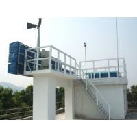
3. High setup test field
As shown in Fig. 1.2, on flat ground, install the receiving/transmitting antenna on top of the cement tower or adjacent high building, make the first zero point of the transmitting antenna pattern point to the ground reflection point, thus the ground reflection is reduced. The distance between two antennas is determined by the far-field condition. The high test field is suitable for parameter testing of the antennas with larger physical dimension. The measuremeant below may reduce or eliminate the reflection of the surrounding environment.
Select the rational transmitting antenna directivity factor to minimum the side-lobe level.
Clear visual obstructions between two antennas.
Take measures to change the reflection wave direction or absorb the reflected energy for the obstructions in the field and the surface reflected wave.
Adopt signal processing technology, e.g., frequency modulation or short pulse wave emission.


