
|
|
[China]

Trade Verify
Address: Block V5, Ronghao Industrial Town, Gaoling District, Xi'an City, Shaanxi Province
Contact name:Gao

Xi 'an West Control Internet Of Things Technology Co., Ltd. |
|
Verified Suppliers
|
|
|
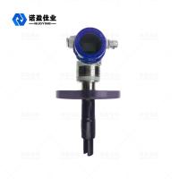
NYDE Tuning Fork Resonance Density Meter 4~20Ma Or RS485 Modbus RTU 24VDC
NYDE Tuning Fork Resonance Density Meter
The NYDE plug-in density meter adopts plug-in installation and is widely used in pipelines. The density of medium in open tanks and closed tanks is directly determined by the vibration frequency received by the tuning fork of the sensor inserted into the medium. The built-in temperature sensor of the sensor provides temperature compensation for it.
Scope of application: The plug-in density meter can perform density detection online in real time. It can be used for process control of products with density as the basic parameter or quality control with solid percentage or concentration percentage as a reference. Typical industries include petrochemical industry, wine industry, food industry, pharmaceutical industry and mineral processing (such as clay, carbonate, silicate, etc.), which are specifically used in the interface detection and mixing of multi-product pipelines in the above industries The density detection, the end-point monitoring of the reactor, and the interface detection of the separator.
NYDE Tuning Fork Resonance Density Meter Technical Parameters
| Measuring range | 0 – 2.5 g /cc (0 – 2500 kg/m3),0~100.0% |
| Calibration range | 0 – 2.5 g /cc (0 – 2500 kg/m3),0~100.0% |
| measurement accuracy | ± 0.002 g /cc (± 2 kg/m3) ,±0.5% |
| Repeatability | ± 0.001 g /cc (± 0.2 kg/m3) ±0.1% |
| Medium temperature range | -50℃~+150℃ |
| Working pressure | 4mpa |
| Fluid viscosity range | 0–600 cP |
| Temperature Coefficient | < 0.1 kg/m3/℃(±0.5%) After correction |
| Stress effect | Negligible |
| Built-in temperature sensor | Digital sensor |
| Wetted material | 316L,2205 Stainless steel,哈 C,Titanium alloy |
| Fork body coating | Standard PTFE or PFA |
| Power supply | 24VDC,≥50 mA |
| Analog signal output | 4-20 mA,0-1000Hz,RS485 Modbus RTU |
| Output accuracy (20℃) | ±0.1% of reading or ± 0.05% FS |
| Output repeatability (-40~+85℃) | ± 0.05% FS |
| Process connection | DIN 50 PN16 DIN 50 PN40 |
| IDF and RJT sanitary | |
| Protection level | IP67 |
| shell | Aluminum alloy |
NYDE Tuning Fork Resonance Density Meter Operating Principle
The sensor works based on the principle of component vibration, and the component part is the part of the tuning fork immersed in the measured liquid. The tuning fork part induces vibration through an internal piezoelectric device fixed at the bottom end of the fork body. The oscillation frequency is detected by a secondary piezoelectric device fixed at the other end of the fork body, and then the signal is amplified by the circuit on the top. The density of the liquid is closely related to the vibration frequency when the measured liquid flows. When the density of the measured liquid changes, the vibration frequency when the liquid flows also changes. Through the following equation, the density of the measured liquid can be accurately calculated.
D= K0+K1T+K2T2
D= Uncalibrated density of the measured medium (kg/m3)
T= Vibration frequency (μ s).
K0 , K1 , K2= constant
In the process of density detection, NYDE plug-in density meter can automatically compensate for the influence of temperature on the density (D) of the measured medium, and pressure has no significant influence on density.
NYDE Tuning Fork Resonance Density Meter Mechanical installation
Unlike the pipe density sensor, the fork part of the plug-in density meter is not completely enclosed.
Pipe wall or container
The boundary effect of the wall on the fluid plus the viscosity effect of the measuring medium itself, these effects will have a certain influence on the measurement calibration of the sensor. In order to overcome these, for different environments, we summarized and set the installation method and pipe diameter in advance to facilitate the selection under the same conditions.
Installation standard | T-shaped side opening plug-in installation | T-shaped side opening retractable installation | |
Instruction | The fork body directly enters the main fluid | The fork body is retracted into the side of the pipeline to avoid the main fluid, and retracted by 25mm | |
| Flow rate | The flow rate through the fork is 0-1m/s | The main pipe flow rate is 1-5m/s | |
| Viscosity range | Max 600Cp | Maximum 100cP (up to 250cP in individual cases) | |
| Temperature | -50-150℃ | -50-150℃ | |
Main pipe size | ≥ Horizontal pipeline 100mm (4″); ≥ Vertical pipe 150mm (4″); |
≥50mm(2″) | |
Shortcoming |
Not applicable to: Unstable flow rate The main pipe diameter is less than DN100 | 1. | Flocculent solution (such as pulp, etc.) |
| 2. | Unstable flow rate | ||
| 3. | Solutions with tapered viscosity | ||
| 4. | The main pipe diameter is less than DN50 | ||
| 5. | Cases where the temperature effect is significant | ||
Calculation of flow rate
V = Q / (1/4 *π *d2) Example: Flow rate 20m3/h, pipe diameter 100mm
V = 20 / 3600 /(1/4 * 3.14 * 0.1 * 0.1)= 0.7 M/s
Installation location
In order to ensure that the density meter can measure accurately and display stability, the flow rate of the measured medium must not be greater than 1m/s, and the diameter of the pipeline where the density meter is installed must be greater than or equal to 159mm. The location of the density meter should be installed as far away as possible from the pump, and the distance should preferably be greater than 5m; When the flow rate is greater than 1 m/s, use the expanded diameter installation. When the flow rate increases by 1m, the pipe diameter of the density meter is increased by 1.5 times. There must be a straight pipe section ≥ 600mm before the instrument and a straight pipe section ≥ 300mm behind the instrument. The fluid is in a laminar state when flowing through the fork body,
As shown in the figure: horizontal installation of horizontal pipeline

Concentric reducer vertical pipe Insert directly into the fluid

Concentric reducer horizontal pipe Horizontal pipe top view


