
|
|
[China]

Trade Verify
Address: E 18Floor Fazhan Build No.13 Easy Huayuan Road Chancheng Area Foshan City.
Contact name:ALLSON

BOGEN PUMPS |
|
Verified Suppliers
|
|
|
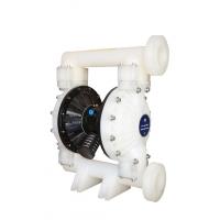
Wastewater Diaphragm Liquid Pump / Self Priming Membrane Water Pump
Diaphragm Liquid Pump Working Principle
In the two symmetrical pump chamber equipped with a diaphragm,
which is connected by a center couplet stem. Compressed air comes
in from pump inlet valve, and enter into one cavity, push the
diaphragm movement, and gases emitted from another cavity. Once to
the destination, gas distribution components will automatically
compressed air into another chamber, push the diaphragm to the
opposite direction, thus make two diaphragm continuous
synchronization to reciprocating movement.
Compressed air goes into the valve, make the diaphragm to the right
movement, and chamber suction make medium enter into, push the ball
into the room, ball valve shuts down due to inhalation, Mediums
discharged by extrusion, and opened the ball valve and at the same
time close the ball valve, prevent back flow, thus to make medium
ceaseless from the entrance inhaled, exit eduction.
Diaphragm Liquid Pump Parameters
| Item | Description | Unit | Reference Figure |
| 1 | Maximum air inlet pressure | Mpa | 0.83 |
| 2 | Maximum flow rate | L/Min | 378 |
| 3 | Maximum lift | M | 70 |
| 4 | Maximum outlet pressure | Mpa | 0.83 |
| 5 | Maximum particle size | mm | 6 |
| 6 | Weight | kg | 23 |
| 7 | Noise level | db | <70 |
Diaphragm Liquid Pump application:
Pneumatic diaphragm pump is a new conveying machine, which is the novel kind of pump. Compressed air as the power source, it can be use in any corrosive liquid, liquid with particle, high viscosity, easy volatile, inflammable, highly toxic liquid.
A 2 5 X X - X X X - X (model selection)
Form of pipe mouth:A-BSP B-NPT(F) C-Flange
Diaphragm material:9 – Santoprene H – Hytrel T - PTFE/Santoprene
Ball material:9 -Santoprene H – Hytre T – PTFE A - Acetal
Ball seat material:P/K –Polypropylene/Kynoar SS –Stainless Steel
Pump material: SS –Stainless Steel AL –Aluminum Alloy CI- Carbon Steel P/K –Polypropylene/Kynoar
Maximum Applied Temperature Limits (diaphragm / ball / seal material)
Acetal ···············································40°- 150°F (4.4- 65.5°C)
Santoprene·········································-40°- 225°F (-40°- 107.2°C) ·················································40°- 220°F (4.4°- 104°C) Nitrile··················································10°- 180°F (-12°- 82°C) Viton···················································-40°- 350°F (-40°-176.6°C) Hytrel··················································-20°-150°F (-12°- 93°C) Kynar··················································10°-200°F (-28.9°- 65.5°C) Polypropylene········································32°- 175°F (0-79.4°C)
Disassembly of the Parts in Fluid Section
a)First, remove the pump from the pipeline system and drain off the materials from the pump inside. b)Place the pump in a clean work environment. c)Dismantle the outlet pipe (1) from the pump first, and then take out the ball (2), O cup (3) and (47) and ball seat (4) from the upper end of the fluid cap (5) in sequence. After that, place the pump upside down and dismantle the inlet pipe (11) so as to take out O cup (3) and (47), ball seat (4) and ball (2) from the fluid cap (5). d)Release the bolts around the two fluid caps to disassemble the cap (5). e)Release the diaphragm screw (10) and remove diaphragm washer (7), (8) and diaphragm (6) from the both ends. Remove the diaphragm rod (23) and the lip-shape seal ring (25) can be replaced. Disassembly of Parts for Air Valve f)Loosen the bolt (39) first, and then dismantle the air valve casing (38), air baffle (42) and sealing gasket (40), and (41). g) Take out the valve slice (36) and valve plate (37) from the air valve casing (38). h) Dismantle the circlip (29) and take out the limit end cap (31) from both ends of the air valve casing (38), and you can replace the cup (30) as needed. i)You can check the lip-type packing (33) after pushing out the spool (35) from the air valve casing (38) with the hands. Disassembly of Parts for Pilot Valve j) Loosen 4 bolts (16) fixing the cylinder head first, and then dismantle the cylinder head (14) and (18) on both ends and remove the O cup (17). k) Remove the sealing gasket (19) from the groove of the motor casing (15). l) Eject the pilot rod (22) and trigger rod (45) from the motor casing (15) and you can replace the lip-type packing (20) on the trigger rod or the O cup (44) on the pilot rod. Reassembly of Diaphragm Pump The reassembly steps of the pump are incompatible with those of disassembly, so you are kindly asked to pay attention to the following in the reassembly process: 1) All the sealing elements, as well as their contact parts, must be greased. 2) Please check carefully prior to the use of all sealing elements whether they are damaged, such as surface damage. If damaged, please replace the new ones. 3) The lip direction of the lip-type packing (20)(, 25) and (33) should be consistent with the direction shown in the chart. 4) The bolts on the fluid cap should alternately be fastened by opposite angles to achieve a better sealing result. Troubleshooting 1. Some fluid is drained from the exhaust opening along with the air flow. Check the diaphragm for any damage. Check the diaphragm screw for looseness 2. There are Air bubbles in the outlet fluid Check the suction pipe connection for good sealing. Check the connection between the suction pipe and the intake manifold for good sealing. Check the O ring between the intake manifold and the fluid cap Check the diaphragm screws for looseness 3. Low pump output Check the air supply is stable. Check the inlet/outlet for any blockage. Check connectors connecting the intake manifold for air tightness Check that the ball is not stuck to the seat or the ball is not improperly seated. 4. Air is discharged from the exhaust opening when there is no reciprocating movement. Check seal ring (33) on slid valve (35). Check seal ring (20) on trigger rod (45). Check seal ring (25) on diaphragm link rod


