
|
|
[China]

Trade Verify
Address: E 18Floor Fazhan Build No.13 Easy Huayuan Road Chancheng Area Foshan City.
Contact name:ALLSON

BOGEN PUMPS |
|
Verified Suppliers
|
|
|
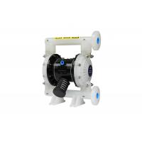
Vacuum Air Powered Dual Diaphragm Pump Non Leakage For Printing
Specifications
Air Diaphragm Pump
1. Non leakage
2. Good self priming performance
3. Convey all kinds of medium
Air diaphragm pump(also know as a Membrane pump, air operated double diaphragm pump(AOOD) or pneumatic diaphragm pump)that uses a combination of the reciprocating action of a rubber,thermoplastic or diaphragm and suitable valves either side of the diaphragm (check valve,butterfly valves,flap valves,or any other form of shut-off valves) to pump a fluid.
| Item | Description | Unit | Reference Figure |
| 1 | Maximum air inlet pressure | Mpa | 0.83 |
| 2 | Maximum flow rate | 1/Min | 192 |
| 3 | Maximum lift | M | 70 |
| 4 | Maximum outlet pressure | Mpa | 0.83 |
| 5 | Maximum particle size | mm | 3 |
| 6 | Weight | kg | 12.3 |
| 7 | Noise level | db | <70 |
BG 2 5 X X - X X- X X (model selection)
Form of pipe mouth:A-BSP B-NPT(F) C-Flange
Diaphragm material:9 – Santoprene H – Hytrel T - PTFE/Santoprene
Ball material:9 -Santoprene H – Hytre T – PTFE A - Acetal
Ball seat material:P/K –Polypropylene/Kynoar SS –Stainless Steel
Pump material: SS –Stainless Steel AL –Aluminum Alloy CI- Carbon Steel P/K –Polypropylene/Kynoar
Maximum Applied Temperature Limits (diaphragm / ball / seal material)
Acetal ···············································40°- 150°F (4.4- 65.5°C)
Santoprene·········································-40°- 225°F (-40°- 107.2°C) ·················································40°- 220°F (4.4°- 104°C) Nitrile···················································10°- 180°F (-12°- 82°C) Viton······················································-40°- 350°F (-40°-176.6°C) Hytrel·····················································-20°-150°F (-12°- 93°C) Kynar······················································10°-200°F (-28.9°- 65.5°C) Polypropylene···········································32°- 175°F (0-79.4°C)
Product Usage
1. Pump peanut butter, kimchi, mashed potatoes, small red sausage,
jam apple pulp, chocolate, etc.
2. Pumping paint, gum, and pigment.
3, adhesives and glue, all types can be pumped.
4, a variety of tiles, porcelain, bricks and pottery glaze.
5. After the oil well is drilled, pump the sediment and grout.
6. Pump various emulsions and fillers.
7. Pumping all kinds of age.
8. Use the pump as the tanker, and the barge clears the tank to
absorb the age.
9, hops and fermented powder slurry, syrup, sugar dense.
10. Pumping water from mines, tunnels, tunnels, beneficiation, and
slag. Pumping cement grout and mortar.
11, a variety of rubber pulp.
12. Various abrasives, corrosives, petroleum and mud, cleaning
grease and general containers.
13, a variety of highly toxic, flammable, volatile liquids.
14, a variety of strong acid, alkali, strong corrosive liquid.
15, a variety of high temperature liquids can withstand 150 ° C.
16. As a pre-stage pressure supply device for various solid-liquid
separation devices
1” Flow diagram

Installation dimensions:

Disassembly of the Parts in Fluid Section
a)First, remove the pump from the pipeline system and drain off the materials from the pump inside. b)Place the pump in a clean work environment. c)Dismantle the outlet pipe (1) from the pump first, and then take out the ball (2), O cup (3) and (47) and ball seat (4) from the upper end of the fluid cap (5) in sequence. After that, place the pump upside down and dismantle the inlet pipe (11) so as to take out O cup (3) and (47), ball seat (4) and ball (2) from the fluid cap (5). d)Release the bolts around the two fluid caps to disassemble the cap (5). e)Release the diaphragm screw (10) and remove diaphragm washer (7), (8) and diaphragm (6) from the both ends. Remove the diaphragm rod (23) and the lip-shape seal ring (25) can be replaced. Disassembly of Parts for Air Valve f)Loosen the bolt (39) first, and then dismantle the air valve casing (38), air baffle (42) and sealing gasket (40), and (41). g) Take out the valve slice (36) and valve plate (37) from the air valve casing (38). h) Dismantle the circlip (29) and take out the limit end cap (31) from both ends of the air valve casing (38), and you can replace the cup (30) as needed. i)You can check the lip-type packing (33) after pushing out the spool (35) from the air valve casing (38) with the hands. Disassembly of Parts for Pilot Valve j) Loosen 4 bolts (16) fixing the cylinder head first, and then dismantle the cylinder head (14) and (18) on both ends and remove the O cup (17). k) Remove the sealing gasket (19) from the groove of the motor casing (15). l) Eject the pilot rod (22) and trigger rod (45) from the motor casing (15) and you can replace the lip-type packing (20) on the trigger rod or the O cup (44) on the pilot rod. Reassembly of Diaphragm Pump The reassembly steps of the pump are incompatible with those of disassembly, so you are kindly asked to pay attention to the following in the reassembly process: 1) All the sealing elements, as well as their contact parts, must be greased. 2) Please check carefully prior to the use of all sealing elements whether they are damaged, such as surface damage. If damaged, please replace the new ones. 3) The lip direction of the lip-type packing (20)(, 25) and (33) should be consistent with the direction shown in the chart. 4) The bolts on the fluid cap should alternately be fastened by opposite angles to achieve a better sealing result. Troubleshooting 1. Some fluid is drained from the exhaust opening along with the air flow. Check the diaphragm for any damage. Check the diaphragm screw for looseness 2. There are Air bubbles in the outlet fluid Check the suction pipe connection for good sealing. Check the connection between the suction pipe and the intake manifold for good sealing. Check the O ring between the intake manifold and the fluid cap Check the diaphragm screws for looseness 3. Low pump output Check the air supply is stable. Check the inlet/outlet for any blockage. Check connectors connecting the intake manifold for air tightness Check that the ball is not stuck to the seat or the ball is not improperly seated. 4. Air is discharged from the exhaust opening when there is no reciprocating movement. Check seal ring (33) on slid valve (35). Check seal ring (20) on trigger rod (45). Check seal ring (25) on diaphragm link rod


