
|
|
[China]

Trade Verify
Address: Kaifull Industrial Part, Goabu Industrial Area, Donguan, Guangdong, China, 523287
Contact name:Bruce Niu

Shenzhen Zion Kaifull Automation Technology Co., Ltd. |
|
Verified Suppliers
|

|
|
1. Product Overview
Step motor is a motor that converts the electrical pulse signal into the corresponding angle displacement or the line displacement. It can use the quantity and frequency of the pulse to control the rotation (rotation angle, rotation speed) in automation applications. For each of the pulse, the motor rotor rotates a angle or forward, and its output angle shift or line displacement is proportional to the input pulse, and the speed is proportional to the pulse frequency. Therefore, step motor is also called pulse motor.
In the case of non-overload, the speed of the motor and the stop position depends only on the frequency and number of the pulsed input, without being affected by the load change. That is to say, add a pulse signal to the motor, and the motor turns a step distance. The advantage of this linear relationship between pulse and angle rotation, plus that a step motor only has periodic errors without cumulative errors, make step motor widely used in automation speed, position and other control fields easily.
With the development of product research and development of technology, the performance of the step system has been even more improved. If the stepper system is not overloaded, there will be no step loss mostly nowadays, and life time very long, almost no need maintenance, which makes steppers popular and widely used in many kinds of industrial automation motion control applications.
Although the stepper motor and its control technology are currently very mature, if not used properly, there may still be a situation of step loss, that is, position error etc. Here, we will analyze some problems and solutions.
Losing pulses when changing direction leads to inaccurate positioning
When changing direction, the pulse is lost, which means that it is accurate in any direction, but as soon as the direction is changed, errors accumulate, and the more times it is changed, the more biased it is.
Solution: Generally, stepper drivers have certain requirements for direction and pulse signals. For example, the direction signal is determined a few microseconds before the first rising or falling edge of the pulse (different drivers have different requirements) arrives. Otherwise, there will be a pulse that runs in the opposite direction of the actual required direction. Finally, the problem will appear as it deviates more and more, with smaller subdivisions becoming more prominent. The main solution is to use software to change the logic of the pulse or add a delay.
The initial speed is too high and the acceleration is too large, which sometimes causes stepping loss.
Solution: Due to the characteristics of the stepper motor, the initial speed should not be too high, especially when the load inertia is large. It is recommended to have the initial speed below 1r/s, so that the impact is small. If the same acceleration is too large, it will also have a large impact on the system, which is simple overshoot
Insufficient motor output torque
Solution: Increase the motor current appropriately, increase the voltage of the progressive driver (pay attention to the optional driver), and choose a motor with higher torque.
Environmental electromagnetic interference causes mis-operation of the controller or driver, resulting in inaccurate positioning.
It is necessary to identify the source of disturbance and reduce its electromagnetic interference on the stepper system, such as increasing spatial distance, using shielded wires for signal lines, and ensuring good grounding of the controller or driver to block communication channels and improve its anti-interference ability.
Solutions:
The Applications of Kaifull PRMCAS Hybrid Stepper Motors
Mainly used in industries, aerospace, robotics, precision measurement and other fields, such as optoelectronic theodolites for tracking satellites, military instruments, communication and radar equipment, the widespread application of subdivision drive technology makes the phase number of motors not limited by step angle, bringing convenience to product design. At present, in the subdivision drive technology of stepper motors, chopping constant current drive, instrument pulse width modulation drive, and current vector constant amplitude uniform rotation drive control are adopted, greatly improving the operating accuracy of stepper motors and promoting the development of stepper motors in the direction of high-speed and precision in medium and low-power applications.
Kaifull hybrid stepper motors are currently widely used in various automation equipment and instruments such as engraving machines, laser machines, CNC machine tools, textile and clothing machinery, medical equipment, measuring equipment, electronic processing equipment, packaging machinery equipment, etc.
In the field of robotics
In the field of robotics, stepper motors are widely used to control the motion and direction of robot arms. By sending pulse signals on the motor, the robot can easily and accurately pick up or place items.
Printing assembly
In the printing and assembly industry, stepper motors achieve high-quality printing and assembly by controlling the movement of rollers, discs, and other moving parts on the printing machine.
Medical devices
In the field of medical devices, stepper motors are used to control the automated positioning and movement of surgical robots and medical equipment.
3D printing
In 3D printing technology, stepper motors can achieve complex 3D structures and shapes by controlling the movement of the print head.
Industrial automation
In the field of industrial automation, stepper motors are widely used in the control of various equipment, such as engraving machines, laser machines, CNC machine tools, textile and clothing machinery, medical equipment, measuring equipment, electronic processing equipment, packaging machinery and other automation equipment and instruments.
In summary, stepper motors have become an indispensable component in various application fields, helping various devices and machines complete complex actions through their stable motion and precise control.
2. Hybrid Stepper Motor General Technical Specifications
| Step Angle | 1.8° (2 Phase) |
| Step Angle Accuracy | 0.09° |
| Shaft Type | Single, Dia. 5mm (Customizable) |
| Max. Temperature Rise | Less than 80 °C (Rated Current) |
| Max. Surface Temperatures | Max Allowed 100℃ |
| Ambient Temperature | -20 °C ~ +50 °C |
| Insulation Grade | 100 MΩ Min. , Class B |
| Dielectric Strengt | 500 VAC for 1 Minute |
| Max. Axial Load | 10N |
| Max. Radial Load | 25N (10mm from mounting Surface) |
| Certificates | Rohs, CE, CCC (As per Customer Need) |
3. Hybrid Stepper motor Performance Datasheet
| Model | Current | Resistance | Inductance | Holding Torque | Detent Torque | Rotor Inertia | Bi/Unipolar | Weight | Length |
| A/Ø | Ω/Ø | mH/Ø | N.m | N.cm | g.cm2 | # of Leads | g | mm | |
| 42HS046-1704S-39 | 1.7 | 2.1 | 4 | 0.46 | 1.5 | 55 | Bi (4) | 280 | 39.5 |
| 42HS046-1204S-39 | 1.2 | 3.9 | 7.8 | 0.46 | 1.5 | 55 | Bi (4) | 280 | 39.5 |
| 42HS046-0854S-39 | 0.85 | 7.9 | 16 | 0.46 | 1.5 | 55 | Bi (4) | 280 | 39.5 |
| 42HS046-0604S-39 | 0.6 | 15.5 | 31 | 0.46 | 1.5 | 55 | Bi (4) | 280 | 39.5 |
4. Mechanical Dimensions (in mm)

5. Matching Connector with Leads Dimenssions

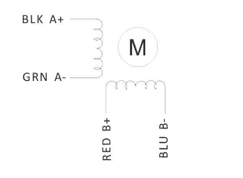
6. Wiring Diagram
7. Torque Speed Curves


