
|
|
[China]

Trade Verify
Address: Kaifull Industrial Part, Goabu Industrial Area, Donguan, Guangdong, China, 523287
Contact name:Bruce Niu

Shenzhen Zion Kaifull Automation Technology Co., Ltd. |
|
Verified Suppliers
|
|
|
1. Products Overview
Stepper motor is an executive agency that converts electrical pulses into angle displacement. You can control the angle by controlling the number of pulse to achieve the purpose of accurate position control. At the same time, you can control the speed and acceleration of the motor by controlling the input pulse frequency to achieve the purpose of the speed control.
Step motor, also called as pulse motor is normally classified by structural as: reactive step motors (VR), permanent magnet step motor (PM), and hybrid step motor (HB). Step motor can also be divided into rotation and straight lines according to the form of movement. According to whether there is an encoder, can be divided as open-loop and closed-loop step motors.
Reactive step motor: there are windings on the stator and rotor consisting of soft magnetic materials. The structure is simple, the cost is low, the step distance is small, and it can reach 1.2 °, but the dynamic performance is poor, the efficiency is low, the heating is large, and the reliability is difficult to guarantee.
Permanent Magnet step motor: The rotor of the permanent magnet step motor is made of permanent magnet material, and the rotor is the same as that of the stator. It is characterized by good dynamic performance and large output torque, but this motor has poor accuracy and large steps (generally 7.5 ° or 15 °).
Hybrid Step motor: Hybrid steaming motor integrates the advantages of reaction and permanent magnets both. It has a multi-phase windings, permanent magnet material on the rotor, and multiple small teeth on the rotor and stator to improve the step accuracy. It is characterized by large output torque, good dynamic performance, and small steps, which can meet automation applications which have high precision requirement.
According to the quantity of phases, there are two -phase, three, and five -phase step motors. The most popular is the two-phase hybrid step motor, accounting for about 97%of the market share. The reason is that the two-phase step motor is more cost-effective, and also has satisfactory performance due to subdivision or micro stepping function of its drive.
The basic step angle of a two-phase step motor is 1.8 °/step. Matched with a half-step drive, the step angle is reduced to 0.9 °. Matched with a micro stepping driver, the step angle can be subdivided up to 256 times (0.007 ° per micro step), which can meet the requirement of most applications.
Kaifull two-phase, three-phase, and five-phase hybrid step motors are made of high-temperature permanent magnet and high-quality cold-rolled steel sheets. Our stepper motors range is very rich, covering 20mm to 150mm in frame size. At the same time, there are all-in-one step motors that integrated with drivers, closed-loop stepper motor, and with brake stepper motor etc..
Generally speaking, the characteristics of step motor are:
Easy drive.
No matter how the input current changes, as long as the load can be driven, the step motor moves according to the minimum angle.
No feedback signal is required. The step motor moves according to the pulse frequency and quantity given by the drive, and does not need to rely on the motor actual status feedback.
The positioning error does not accumulate. The reason why the stepping motor does not accumulates is because it does not need to know the actual location, but only needs to know the number of rotating steps. Therefore, the step motor only needs to receive the signal of each step, and then move according to the step angle. It is not necessary to know the starting location or target location. This can avoid the problem of accumulating errors. In addition, the working principle of the stepper motor makes the movement discrete and performed from a specific angle without a continuous accumulation error.
Stepper motor driver principle is simple and easy to develop control system.
Step motor has the characteristics of high power density, high output torque, low noise, low vibration and smooth rotation, high energy conversion efficiency, stable and reliable, long life etc. At the same time, our company supports the flexible customization, too.
Kaifull hybrid stepper motors are mainly used in digital control systems, with high accuracy and reliable operation. If position detection and speed feedback are used, closed-loop control can also be achieved. Stepper motors have been widely used in digital control systems, such as digital to analog conversion devices, CNC machine tools, computer peripherals, automatic recorders, clocks, etc. In addition, they have also been applied in industrial automation production lines, printing equipment, etc.
The application scenarios of Kaifull stepper motors are very wide, and the following are some application examples:
Industrial field: Stepper motors are used in automotive instrumentation, machine tool automation production equipment, robot manufacturing, inspection, and process flow.
Security field: Used for monitoring products, such as PAN/ZOOM/TILT for security cameras.
Medical field; Hydraulic pumps, ventilators, and blood analyzers used in medical scanners, samplers, digital oral photography.
In the field of consumer electronics, it is used in various stages of electronic product production, such as solder paste printing, SMT placement, reflow soldering, visual inspection, production of cables with terminals, dispensing machines, screen laminating machines, 3D printers, etc.
Precision equipment and instruments: used in ATM machines, inkjet printers, engraving machines, photo machines, spray painting equipment, computer peripherals and massive data storage devices, precision instruments, industrial control information systems, office automation, robots and other fields, especially suitable for applications with smooth operation, low noise, fast response, long service life, and high output torque.
Textile machinery: It is widely used in textile machinery equipment such as computerized embroidery machines. These stepper motors have the characteristics of low torque retention, fast response speed, low operating noise, stable operation, good control performance, and low overall cost.
Flat mobile devices: such as laser cutting machines, printers, scanners, etc.
Measurement instruments: such as high-precision 3D scanners, optical measurement equipment, etc.
Medical equipment: used for medical and surgical instruments, etc.
Camera lens. Used for focusing and moving optical devices, etc.
These application scenarios typically require stepper motors to have characteristics such as high precision, low noise, fast response, and long lifespan to meet the positioning, control, and performance requirements of different industries.
2. Hybrid Stepper Motor General Technical Specifications
| Step Angle | 1.8° (2 Phase) |
| Step Angle Accuracy | 0.09° |
| Shaft Type | Single shaft, Dia. 14 or 12.7mm (Customizable) |
| Max. Temperature Rise | Less than 80 °C (Rated Current) |
| Max. Surface Temperatures | Max Allowed 100℃ |
| Ambient Temperature | -20 °C ~ +50 °C |
| Insulation Grade | 100 MΩ Min. , Class B |
| Dielectric Strengt | 1500 VAC for 1 Minute |
| Max. Axial Load | 60N |
| Max. Radial Load | 15N (15mm from mounting Surface) |
| Certificates | Rohs, CE, CCC (As per Customer Need) |
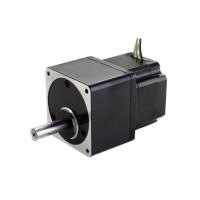
3. Hybrid Stepper motor Integrated with Gearbox Performance
Datasheet
| Model | Gear Output Torque N.m | Reduction Ratio | Step Degree Gear Side | Current A/Ø | Resistance Ω/Ø | Inductance mH/Ø | Rotor Inertia g.cm2 | Bi/Unipolar # of Leads | Weight Kg | Length Incld. Gear mm |
60AHS100 -2006GR3.6 -82 | 1. 0 | 1:3.6 | 0. 5 | 2.0 Half | 1.1 | 1.1 | 135 | Bi(6) | 0.8 | 82 |
60AHS200 -2006GR7.2 -82 | 2. 0 | 1:7.2 | 0. 25 | 2.0 Half | 1.1 | 1.1 | 135 | Bi(6) | 0.8 | 82 |
60AHS250 -2006GR9 -82 | 2. 5 | 1:9 | 0. 2 | 2.0 Half | 1.1 | 1.1 | 135 | Bi(6) | 0.8 | 82 |
60AHS270 -2006GR10 -85 | 2. 7 | 1:10 | 0. 18 | 2.0 Half | 1.1 | 1.1 | 135 | Bi(6) | 0.8 | 82 |
60AHS300 -1406GR18 -82 | 3. 0 | 1:18 | 0. 1 | 1.4 Full | 2.2 | 4.4 | 135 | Bi(6) | 0.8 | 82 |
60AHS400 -1406GR36 -82 | 4. 0 | 1:36 | 0. 05 | 1.4 Full | 2.2 | 4.4 | 135 | Bi(6) | 0.8 | 82 |
60AHS400 -1406GR50 -82 | 4. 0 | 1:50 | 0. 036 | 1.4 Full | 2.2 | 4.4 | 135 | Bi(6) | 0.8 | 82 |
60AHS400 -1406GR100 -82 | 4. 08 | 1:100 | 0. 018 | 1.4 Full | 2.2 | 4.4 | 135 | Bi(6) | 0.8 | 82 |
4. Mechanical Dimensions (in mm)
5. Wiring Diagram
6. Torque Speed Curves


