
|
|
[China]

Trade Verify
Address: Shenzhen YingSheng Technology Co., Ltd 805, Tongxin Technology Building, Qiaotou Community, Fuhai Street, Baoan District, Shenzhen
Contact name:Zhou

Shenzhen Yingsheng Technology Co., Ltd. |
|
Verified Suppliers
|

|
|
Copper Base Boards Need Gerber File Metal Pcb For Electronic Regulator
YScircuit Produce High-Performance Copper PCB
The copper PCB (or copper core PCB) is stacked up by copper core, insulated layer and copper circuit layer, mainly used for high-frequency equipment, some communication equipment, high-power LED products, and other products required high thermal conductivity.

| Metal core PCB type | Normal single sided Aluminium based pcb, Double sided Aluminum pcb, FR4+Aluminium mixed backed circuit boards, Chip on board LED Alumnum pcb or copper pcb (COB MCPCB), Copper substrate pcb, LED PCB; |
| Board Material | Bergquist Aluminium material, Aluminum Base,Copper Base |
| LED PCB Max Dimension | 1900mm*480mm |
| Min Dimension | 5mm*5mm |
| Min Trace& line spacing | 0.1mm |
| Warp & Twist | <0.5mm |
| Finished MPCB Thickness | 0.2-4.5 mm |
| Copper Thickness | 18-240 um |
| Hole Inner Copper Thickness | 18-40 um |
| Hole Position Tolerance | +/-0.075 mm |
| Min Punching Hole Diameter | 1.0mm |
| Min Punching Square Slot Specification | 0.8mm*0.8mm |
| Silk Prints Circuit Tolerance | +/-0.075 mm |
| Outline Tolerance | CNC:+/-0.1mm; Mould:+/- 0.75mm |
| Min Hole Size | 0.2 mm (No limitation in Max hole dimention) |
| V-CUT Angle Deviation | +/-0.5° |
| V-CUT Board Thickness Range | 0.6mm-3.2mm |
| Min Component Mark Character Style | 0.15 mm |
| Min Open Window for PADs | 0.01mm |
| Solder Mask color | Green, White, Blue, Matte black, Red. |
| Surface Finishing | HASL, OSP, HASL LF, ENIG, ENEPIG (Electroless Nickel Electroless Palladium Immersion Gold) |
| layer/m² | S<1㎡ | S<3㎡ | S<6㎡ | S<10㎡ | S<13㎡ | S<16㎡ | S<20㎡ | S<30㎡ | S<40㎡ | S<50㎡ | S<65㎡ | S<85㎡ | S<100㎡ |
| 1L | 4wds | 6wds | 7wds | 7wds | 9wds | 9wds | 10wds | 10wds | 10wds | 12wds | 14wds | 15wds | 16wds |
| 2L | 4wds | 6wds | 9wds | 9wds | 11wds | 12wds | 13wds | 13wds | 15wds | 15wds | 15wds | 15wds | 18wds |
| 4L | 6wds | 8wds | 12wds | 12wds | 14wds | 14wds | 14wds | 14wds | 15wds | 20wds | 25wds | 25wds | 28wds |
| 6L | 7wds | 9wds | 13wds | 13wds | 17wds | 18wds | 20wds | 22wds | 24wds | 25wds | 26wds | 28wds | 30wds |
| 8L | 9wds | 12wds | 15wds | 18wds | 20wds | 20wds | 22wds | 24wds | 26wds | 27wds | 28wds | 30wds | 30wds |
| 10L | 10wds | 13wds | 17wds | 18wds | 20wds | 20wds | 22wds | 24wds | 26wds | 27wds | 28wds | 30wds | 30wds |
| 12L | 10wds | 15wds | 17wds | 18wds | 20wds | 20wds | 22wds | 24wds | 26wds | 27wds | 28wds | 30wds | 30wds |
| 14L | 10wds | 16wds | 17wds | 18wds | 20wds | 20wds | 22wds | 24wds | 26wds | 27wds | 28wds | 30wds | 30wds |
| 16L | 10wds | 16wds | 17wds | 18wds | 20wds | 20wds | 22wds | 24wds | 26wds | 27wds | 28wds | 30wds | 30wds |
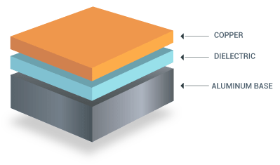
Single Layer Metal Core PCB Stack up
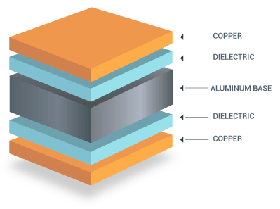
Double Layer Metal Core PCB Stack up
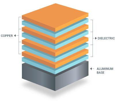
Multilayer Metal Core PCB Stack up


FQA
1. What is the thickness of a metal core PCB?
The thickness of the metal core in a PCB substrate is typically 30
mil - 125 mil, but thicker and thinner boards are possible.
2. What are the advantages of metal core board?
Metal core boards transfer heat 8 to 9 times faster than FR4 PCBs.
These metal core laminates keep heat-generating components cool by
dissipating heat faster.
The dielectric material is kept as thin as possible in order to
create the shortest path from the heat source to the metal
backplane.
3. How is a metal core PCB made?
If the board is a single-layer board with no layers transitioning
back to the metal plate, the dielectric layers can be pressed and
bonded to the metal plate using the standard process used with FR4
dielectrics.
4. What is a metal core PCB?
A metal core printed circuit board (MCPCB) is a printed circuit
board that contains base metal materials.
The core is designed to transfer heat away from components that
generate a lot of heat.


