|
|
[China]

Trade Verify
Address: Shenzhen YingSheng Technology Co., Ltd 805, Tongxin Technology Building, Qiaotou Community, Fuhai Street, Baoan District, Shenzhen
Contact name:Zhou

Shenzhen Yingsheng Technology Co., Ltd. |
|
Verified Suppliers
|

|
|
High Quality Pcb Board Customize Aluminum Pcb Board For Led High Bay Light
All you need to do is connect the chip to a power supply through the positive and negative terminals present on the PCB, and the LED circuit board will light up instantly.
PCBS FOR THE LED INDUSTRY
Printed circuit boards, or PCBs, are everywhere in our
technology-based society.
Everything from computers to medical equipment to cars contains PCBs in one form or another.
However, PCBs are not all the same— each product is custom with different designs or materials and specifications to suit a unique purpose.
For circuit boards in the LED industry, the base material is especially important, which helps determine how effectively the circuit board transfers heat.
Some applications require specific properties in their circuit boards.
This is especially true for temperature-sensitive applications, one of which is LED lighting.
The LED lighting industry is expanding rapidly in response to increased interest in the more efficient and cost-effective lighting method, but much of the functionality of LED lights depends on the temperature of its system.
For many companies, the solution to this problem is aluminum-based PCBs.
To help you understand why the LED lighting industry uses PCBs, we’ve outlined the nature of base layers, the benefits of aluminum circuit boards and why they work well in the LED lighting industry.
WHAT IS AN LED PCB?
LED stands for light-emitting diode.
An LED printed circuit board is used to mount the diode(s) and
power the LED for the application.
Generally, LED devices use a surface-mounted design (SMD) that
includes a single LED component.
To generate more light, an LED circuit board connects multiple
lights.
Because these lights and their operation generate a large amount of
heat, they need to have a way to remove this heat, such as a heat
sink or structural material that draws away heat.
Hence, the LED PCB material may be aluminum, which excels at
transferring heat away from the board.
Due to the many advantages of LED lighting and its multiple applications in modern life, LED PCB manufacturing and products have increased to meet the rising demand.
FACTORS TO CONSIDER WHEN DESIGNING AN LED PCB BOARD
When designing an LED printed circuit board, you must think about
the materials used, how to manage heat, trace routing and the
finish.
With an appropriate design, a PCB manufacturer can create a board
that will work as it should for operating the LED.
MATERIALS
Materials used for the printed circuit board should work together
to remove and dissipate extra heat, insulate conductors, and allow
electrical connections between LED components.
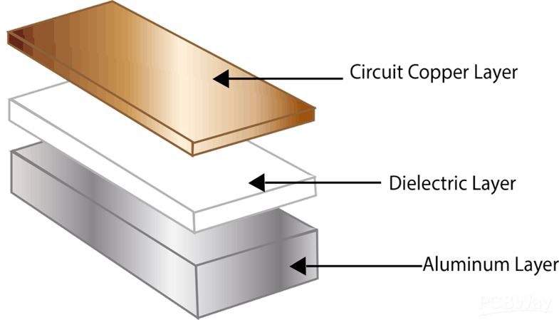
The base layer for many LED circuit boards uses aluminum.
Over the aluminum base is the dielectric layer, topped by the
copper circuit layer and the solder mask.
This type of structure also goes by the term insulated metal
substrate (IMS).
The aluminum base works well to release extra heat and assist in
thermal management.
THERMAL MANAGEMENT
Thermal management is one of the most crucial aspects of LED
design.
Poorly regulated temperatures can shorten the life of the device
and affect the color purity of the light.
Therefore, designs of LED circuit boards typically include aluminum
cores and heat sinks to get as much heat away from the components
as possible.
The component arrangement and LED placement also impact the
distribution and removal of heat to the air and should be part of
the design considerations.
TRACE ROUTING
Proper trace routing design prevents open and short circuits,
crosstalk between circuits and manufacturing problems.
Trace routing ensures that all network connections are properly
attached without interference from other network connections.
Using the proper width of the traces prevents overheating.
Space for traces and mounting hole considerations in the design
also ensure that problems will not happen during manufacturing.
FINISH
The board’s finish protects the circuit layer and ensures that
assembly has a site for soldering components onto.
There are several types of printed circuit board finishes
available, each with its own advantages and disadvantages.
Finding the right finish may involve discussing the expectations of
the board and the budget for the project.
LED printed circuit board cores typically include either standard
epoxy glass or metal cores. Heat transfer, as always, is crucial to
maintaining the life of LED circuit boards.
However, epoxy glass cores can be more cost-effective.
METAL CORE
The most common metal core used for LED printed circuit boards is
aluminum.
This metal quickly transfers heat away from the board to the
outside.
In doing so, it augments the function of the board’s heat sink in
preventing excessive heat from damaging the components of the
circuit board.
These types of PCBs require surface mounted components because
mounting anything through the board could lead to short circuits if
the solder contacts the metal interior of the circuit board.
However, since LED components are surface mounted, metal cores
suffice for their use.
STANDARD GLASS EPOXY
One of the biggest differences between metal and glass cores is
their method of heat transfer.
For instance, metal cores do not use metal vias to conduct heat.
Instead, the aluminum does the work. For standard glass epoxy,
metal vias carry heat away, though not as efficiently as metal core
PCBs.
Unless cost-effectiveness is the most important component of
designing an LED PCB, metal cores will perform better than standard
glass epoxy cores.
| Layer | 1-24 |
| Material | Aluminum core (Domestic 1060), Copper core, FR4 covering |
| Thickness (Finished Board) | 0.8 mm-5.0 mm |
| Max. Board Size | 610 mm*610 mm |
| Copper weight (finished) | 0.5 oz-4.0 oz |
| Surface Finish | Hot air solder leveling (HASL) Lead-free HASL: RoHS compliant Electroless nickel/immersion gold (ENIG): RoHS compliant |
| Min. Tracing/Spacing | 4 mil/4 mil |
| Min. diameter of drill | 8mil |
| Min. Annular ring | 4mil |
| Soldermask Color | Green, red, black, yellow, white, blue, green matt, black matt |
| Silkscreen Legend Color | White, Black, Yellow |
| Countersink holes | Yes |
| Screw holes | Yes |
| layer/m² | S<1㎡ | S<3㎡ | S<6㎡ | S<10㎡ | S<13㎡ | S<16㎡ | S<20㎡ | S<30㎡ | S<40㎡ | S<50㎡ | S<65㎡ | S<85㎡ | S<100㎡ |
| 1L | 4wds | 6wds | 7wds | 7wds | 9wds | 9wds | 10wds | 10wds | 10wds | 12wds | 14wds | 15wds | 16wds |
| 2L | 4wds | 6wds | 9wds | 9wds | 11wds | 12wds | 13wds | 13wds | 15wds | 15wds | 15wds | 15wds | 18wds |
| 4L | 6wds | 8wds | 12wds | 12wds | 14wds | 14wds | 14wds | 14wds | 15wds | 20wds | 25wds | 25wds | 28wds |
| 6L | 7wds | 9wds | 13wds | 13wds | 17wds | 18wds | 20wds | 22wds | 24wds | 25wds | 26wds | 28wds | 30wds |
| 8L | 9wds | 12wds | 15wds | 18wds | 20wds | 20wds | 22wds | 24wds | 26wds | 27wds | 28wds | 30wds | 30wds |
| 10L | 10wds | 13wds | 17wds | 18wds | 20wds | 20wds | 22wds | 24wds | 26wds | 27wds | 28wds | 30wds | 30wds |
| 12L | 10wds | 15wds | 17wds | 18wds | 20wds | 20wds | 22wds | 24wds | 26wds | 27wds | 28wds | 30wds | 30wds |
| 14L | 10wds | 16wds | 17wds | 18wds | 20wds | 20wds | 22wds | 24wds | 26wds | 27wds | 28wds | 30wds | 30wds |
| 16L | 10wds | 16wds | 17wds | 18wds | 20wds | 20wds | 22wds | 24wds | 26wds | 27wds | 28wds | 30wds | 30wds |


FQA
1. The advantages of LED PCB
With the electronic products is more and more smaller and thinner,
making it popular to use LED PCB, and there are various advantages
with using LED PCB as follows:
There are two main reasons which make the LED PCB be popular in addition to increasing the light output of the fixture with integrating multiple LED components.
2. SMD LEDs in your PCB
There are many devices including LEDs on a PCB using surface
mounted components.
If the wires are quite thin, through hole components can bend
slightly so that it looks cheap from the outside.
If making it right to solder the SMD LED, it will be rigid on the
board. What’s more, it can also place the SMD LED behind a screen,
and cheaper LED that use a bulb will stick out through the
packaging.
So it can place the SMD LED behind a small screen in your packaging
to be cleaner for your device.
As you know, many PCBs that contain LEDs are fabricated with
multilayer FR-4 substrates, so you need to have a pattern of
closely-spaced filled or plated through vias under each component
so that it can transmit heat, as well as get to your power and
ground layers.
If your LEDs have a small footprint and are surfaced mounted, it
can use our vias.
Probably there will be a weak solder joint or even tombstoning
because it doesn’t fill or plate over the vias and then solder can
wick into the vias during assembly, so the reason why it’s better
to just use SMD LEDs on an LED lighting array is that the problem
with wicking.
A single LED with decent power output will not lead to damaging to
your board because of undue thermal.
However, if you are going to have a system for lighting
applications, it will need to suffer from a massive heat for the
board that supports your LEDs, and make it hard to cool with
traditional methods for the boards.
Because the individual LEDs are too small, you can’t really attach
a heatsink anywhere, and a heatsink will block the emitted light
anyways.
Because there is a great demand on thermal, the boards with a metal
core are usually used in LED lighting applications due to their
ability to dissipate a great deal of heat.
In general, aluminum is used for LED lighting applications as the
metal core in PCB.
What’s more, aluminum is the most metal used as the core among all
the possible metal core PCBs.
As well as copper and iron are used for metal core PCBs.