

Active Member
|
[China]

Address: No.119 JianShe Road,luoyang,Henan,China 471039
Contact name:Dave Lee

LUOYANG MONTON BEARING SCIENCE & TECHNOLOGY CO.,LTD. |
|
|
RE14016UUCC0P5
RE14025UUCC0P5
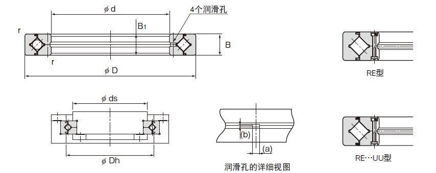
| Shaft diameter | Model No. | Major dimensions | Shoulder dimensions | Basic load rating (radial) | Mass | ||||||||
| Inner diameter d | Outer diameter D | Roller pitch circle diameter dp | Width B B1 | Greasing hole | rmin | ds | Dh | C kN | C0 kN | kg | |||
| a | b | ||||||||||||
| 140 | RE14016 | 140 | 175 | 160 | 16 | 3 | 1.6 | 1 | 147 | 162 | 25.9 | 50.1 | 1 |
| 140 | RE14025 | 140 | 200 | 172 | 25 | 3.5 | 2 | 1.5 | 154 | 185 | 74.8 | 121 | 2.96 |
Procedure for Assembly
When assembling the Cross-Roller Ring, follow the steps below.
[Preparations before assembly]
(1) Thoroughly clean the housing and other assembly parts, and make
sure there are no burrs.
(2) Loosen the bolts that prevent separation of the Cross-Roller
Ring.
(3) If the two divided parts of the outer or inner ring are
misaligned at the joints, correct the misalignment
by gently hitting the ring with a plastic hammer or the like, and
then install it. (For a type secured with rivets, install it
as-is.)
[Installing the Cross-Roller Ring into the Housing or onto the
Shaft]
Since the Cross-Roller Ring has a thin-walled structure, it is
easily tilted during insertion. Use a plastic hammer or similar
tool to level the Cross-Roller Ring by gradually hammering the
perimeter while inserting. Carefully hammer until the sound of the
ring coming into full contact with the mounting surface can be
verifi ed.
Note) When inserting the inner ring, hammer the inner ring. When
inserting the outer ring, hammer the outer ring.
[Assembly directions for RU]
Model RU has insertion holes for installing rollers in the outer
ring. (Filler plugs are attached.) Position the
mounting direction so that the fi ller plugs do not overlap with
the area under maximum load. (The periphery
of the plugged section is slightly recessed, and a fi xing pin is
driven into its side.)
[Assembly directions for RA-C]
The outer ring of model RA-C has a slit for installing rollers.
Position the mounting direction so
that the split section does not overlap with the area under maximum
load. (The split section has two
small holes on the side marked with the product name.)
[Attaching the Presser Flange]
(1) Fit the presser fl ange to the single piece ring (inner ring on
models RB/RA , outer ring on model
RE). In case of model RU, fi t the presser fl ange to the
rotational axis side.
(2) Place the presser fl ange onto the Cross-Roller Ring. Rock the
fl ange several times to match the
bolt holes. Also in case of model RU, rock the fl ange several
times to match the bolt holes.
(3) Insert the presser bolts into the holes. Manually turn the
bolts and make sure they do not show
skewing caused by misalignment of the holes.
(4) Fasten the presser bolts in three to four steps from loose to
fully fastened by tightening the bolts
in a diamond pattern, as shown in Fig. When tightening the
separated inner or outer ring, reciprocating
the single piece outer or inner ring approximately four to fi ve
times (about 90°) will correct
misalignment between the ring and the body.
RE type is two pieces Inner Ring Type for Rotation.
Having the same major dimensions as model RB, this model is usedin
locations where the rotation accuracy of the outer ring is
required.
This type cross roller bearing allows just one bearing to receive
loads in all directions including radial, axial and moment loads.
High Rotation Accuracy
The spacer retainer fi tting among cross-arrayed rollers prevents
rollers from skewing and the rotational
torque from increasing due to friction between rollers. Unlike
conventional types using steel
sheet retainers, the Cross-Roller Ring does not cause unilateral
contact of roller or seize. Thus,
even under a preload, the Cross-Roller Ring provides stable
rotation torque.
Easy Handling
The inner and outer rings, which are separable, are secured to the
Cross-Roller Ring body after
being installed with rollers and spacer retainers in order to
prevent the rings from separating from
each other. Thus, it is easy to handle the rings when installing
the Cross-Roller Ring.
Skewing Prevention
The spacer retainer keeps rollers in their proper position, thereby
preventing them from skewing
(tilted rollers). This eliminates friction between rollers, thus
allowing the smooth motion to be
achieved.
Increased Rigidity
The rollers are arranged crosswise to the adjacent roller, so one
bearing can receive the load in
each direction. It increases the rigidity to three to four times
greater than the conventional type comparedwith the angular ball
bearings installed in double rows.
RE series model is shaped by the RB generated new style design ,
the main dimensions and XRB same type . Its structure is split
inner ring is the type ,the outer ring is the one designed for
applications requiring high precision rotation of the outer parts.
With the Cross-Roller Ring, cylindrical rollers are arranged
crosswise, with each roller perpendicular to the adjacent roller,
in a 90゜V groove, separated from each other by a spacer retainer.
This design allows just one bearing to receive loads in all
directions including, radial, axial and moment loads.
Since the Cross-Roller Ring achieves high rigidity despite the
minimum possible dimensions of the innerand outer rings, it is
optimal for applications such as joints and swiveling units of
industrial robots,swiveling tables of machining centers, rotary
units of manipulators, precision rotary tables, medicalequipment,
measuring instruments and IC manufacturing machines.
Applications :
1 Welding robot
Device overview: Robot for welding work in
automobile manufacturing lines, etc.
Location: rotation shaft of each joint
2 LCD panel transport robot
Device overview: Glass transport robot in
LCD TV manufacturing lines
Location: rotation shaft of each joint
3 Semiconductor wafer transport robot
Device overview: Wafer transport robot in
semiconductor manufacturing lines
Location: rotation shaft of each joint
4 Vertical machining center
Device overview: Machine tool (machining
center)
Location: Rotation shaft of B and C shafts
5 Vertical complex grinder
Device overview: Machine tool (grinder)
Location: Rotation shaft of the table
6 Precision automatic rotation stage
Device overview: Precision rotation stage for
measurement instrument
Location: Rotation shaft of the table
7 Broadcast camera
Device overview: Camera robot for TV broadcast
Location: Rotation shafts of the camera tilt shaft
and pan shaft
8 DD motor
Device overview: DD motor for the drive of
the semiconductor device
Location: Motor rotation shaft


