
|
|
[China]

Trade Verify
Address: Room1148-1422,Dujuan Road,Yuelu area,Changsha,Hunan,China
Contact name:Leo Zeng

Deligreen Power Co.,ltd |
|
Verified Suppliers
|
|
|
Product: Deligreencs BMS16S BMS 200A For 48V 58.4V Lithium LifePO4 Battery Pack
16S 48V 200A LifePO4 BMS Protection Board with Balance and Waterproof For 58.4V LFePO4 Cell Module
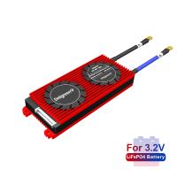
(3.2V rated LiFePO4 battery pack only)
common Version : common port for charge/discharge, charge current default as 100A
separate Version : separate port for charge/discharge, charge current default as 50A
What advantage of the BMS?
1. Use top quality (A-level) protective integrated circuit IC, from the solution of Seiko of Japan.
2. Strong load ability, use high voltage resistance, low inner resistance power Mosfet. The heat sink will greatly help cooling.
3. IC itself has power balancing function. The circuit is simple and reliable.
4. Typical voltage detection for each cell. So each battery will be prevented over charged or over discharged. Over current and short circuit protection function is very reliable.Long time short circuit of the load won't affect the PCB and the battery.Temperature protection can be added.
5. Extreme low power consumption. The consumption of the whole device is less than 50uA.
6. PCB use high anti-corrosion, high water resistance, high impedance ESD conformal Coating.
How to choose the suitable BMS?
You need to make sure of following information
1. Battery type:LifePO4,LTO, Li-NCM battery.
2. Battery pack configuration: No. of series and paralles
3. Constant dischage current: the constant discharge current of your application
4. Constant charge current: the constant charge current of your application
5. Peak discharge current:the highest discharge can a BMS stand
6. Limitation of the controller
Wire Specification
| Current | Wire | Square |
| 10-15A | 16AWG | 1.3mm² |
| 20A | 14AWG | 2mm² |
| 30A | 12AWG | 3.4mm² |
| 40A-60A | 10AWG | 5.3mm² |
| 80A | 8AWG | 8.3mm² |
| 100A | 7AWG | 12mm² |
| 120A-150A | 6AWG | 16mm² |
| 200A-250A | 6AWG*2 | 16mm²*2 |
| 400A | 2AWG*2 | 35mm²*2 |
Important Specification
| Datasheet for 3.2V LifePO4 BMS( 80A-250A ) | |||||||||
| Content | Spec | Unit | Remark | ||||||
| 80A | 100A | 120A | 150A | 200A | 250A | ||||
| Discharge | constant discharge current | 80 | 100 | 120 | 150 | 200 | 250 | A | |
| Over-discharge current protection | 250±50 | 300±50 | 400±100 | 500±10 | 600±100 | 600±100 | A | ||
| charge | charge voltage | Series No. * 3.65 | V | ||||||
| charge current | 40 | 50 | 60 | 75 | 100 | 125 | A | Common port | |
| charge current | 50A as default | A | Separate port | ||||||
| Over charge protection | over charge volt | 3.75±0.025 | V | ||||||
| over charge volt protect delay | 1 | S | |||||||
| Over charge volt release | 3.55±0.05 | V | |||||||
| Power balancing | Power balance volt | 3.5 | V | ||||||
| balance release volt | 3.5 | V | |||||||
| balance current | 35±5 | mA | |||||||
| Over discharge protection | Over discharge detect volt | 2.2±0.1 | V | ||||||
| Over discharge detect delay | 1 | S | |||||||
| Over discharge volt release | 2.7±0.05 | V | |||||||
| Over current protection | Over current detect delay | 1 | MS | ||||||
| Over current protect release | Off-load | ||||||||
| Short circuit protection | Short circuit protection | External load short circuit | |||||||
| Short circuit detect delay | 250 | uS | |||||||
| Short circuit detect release | Off-load | ||||||||
| Temperature protection | Temp protection | charge<0℃, discharge>70℃ | ℃ | Can be customized | |||||
| resistance | Main circuit resistor | ≤20 | mΩ | ||||||
| Self-consumption | Working current | 100 | uA | ||||||
| Sleepy current(when battery is over discharged ) | ≤20 | uA | |||||||
| Working temp | temp range | -40~80 | ℃ | ||||||
| Storage temp | Temp range | -40~80 | ℃ | ||||||
BMS wiring directions
First, Preparation before installation.
Make sure the batteries are of good consistency.The volt difference is no more than 0.05V,inner resistance is no more than 5mΩ,capacity difference lower than 30mAh. Connect the batteries in parallel first and then in series.the better performance of batteries consistency is, the higher performance of the BMS.
Second, wiring instructions.
Attention: please use our wires for our BMS.Don’t use other factories’ wires which can’t match with our BMS.
Step 1 B-(blue thick wire): Connect to battery pack total negative pole -
Step 2, Disconnect the wires for batteries from the BMS side.
Step 3,Connect the wires to batteries. Start from the thick black wire to total negative pole(B1-),then connect the 2nd red thin wire to the 1st battery positive pole(B1+)
B2+,B3+B4+......till the last red thick wire.
Step 4,Finishing all the wires to each batteries,don’t plug into the BMS directly. We suggest you use multimeter measure the voltage of two adjacent metal terminals(You can see the white connector with silver metal pins on the BMS).if the voltage is 3.0~4.2V(LiNCM),2.0~3.6V(LiFepo4), 1.5~2.75V(LTO),which means the wiring is correct.
Step 5,Ensure the wires are connected to batteries correctly, all voltage is normal, you can plug the wires into the BMS.
Step 6 P-: Connect P-(black thick wire) to load - and charger -
(if you ordered “common port”)
Charger+ connect to C-(yellow wire) load+ connect to P-(Black thick wire)
(if you ordered “separate port”)
Step 7 charger+ and load+ connect to battery +,please use thick wire
Third, Measure the total volt of the pack, and the output voltage of the BMS.if the voltage is the same,it means the wiring is correct.You can use the BMS now. Otherwise please check the wiring again according to the tips above.
How to test if the bms is good or not?
1. Make sure to use the attached detective wires of our bms.
Ensure volt-detect red wires are connected correctly.
2. Connect the wire to the battery pack,measure the voltage through the wire,it should be equal with the voltage of each cell.
If the votage is different,it means wrong wiring.
3. Make sure the voltage is same,plug the bms in.Make the multimeter point to Ω, measure the resistance between P- and B-. If the resistance is 0, then the BMS is good.
◆ The cable starts from the black thin wire connecting B-, the second wire (the thin red wire) is connected to the positive pole of the first battery, and the positive pole of each battery is connected in turn until the last red wire is connected to B+;
◆ After connecting the wire, mustn't insert the plug directly into the BMS. Measure the voltage between each two adjacent metal terminals on the back of the plug. If the voltage of the terpolymer battery should be between 2.8V and 4.2V, the iron-lithium battery should be between 2.5V and 3.65V.
◆ After correct wiring sequence and voltage confirmation, insert the BMS socket.
◆ The protective board B line (blue thick line) is connected to the negative pole of the battery pack.
◆ After the wiring is completed, measure whether the total voltage of the battery pack and the total voltage passing through the BMS are equal. If they are different, check again according to the above wiring sequence.


