Industrial Yaskawa Sigma 2 Series New 100W AC SERVO MOTOR
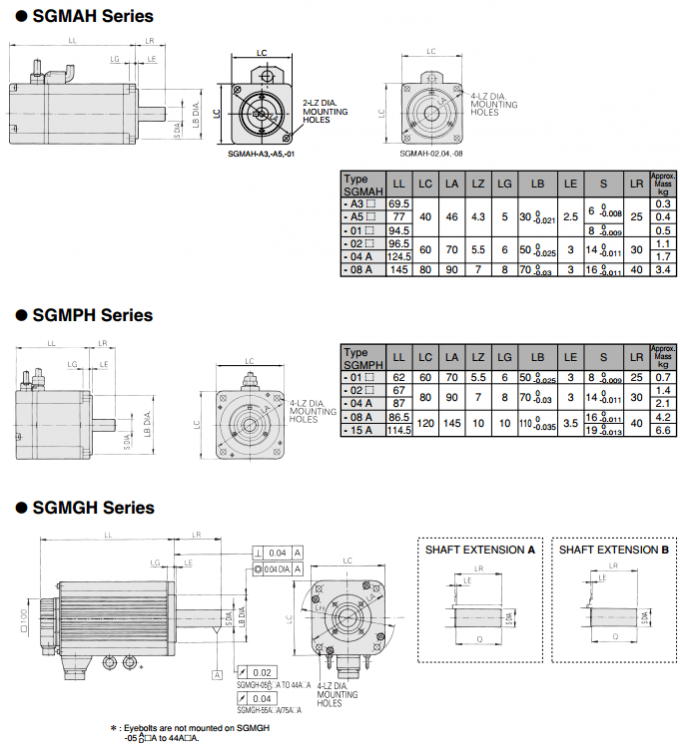
SGMPH-01A1A41
DESCRIPTION
- Yaskawa Electric
- AC Servo Motor
- Sigma 2 (Σ-II Series)
SEPCIFICATIONS
| Manufacturer | Yaskawa / MagneTek / Saftronics / Omron |
| Series | Sigma 2 (Σ-II Series) |
| Weight | 5KG |
SIMILAR PRODUCTS
| SGMPH-02A1A-YR12 | SGMPH-02A1A-YR21 |
| SGMPH-02A1A-YR31 | SGMPH-02A1A-YR32 |
| SGMPH-02A2A-YR12 | SGMPH-02A2A-YR21 |
| SGMPH-02AAA2B | SGMPH-02AAA2C |
| SGMPH-02AAA2E | SGMPH-02AAA2E |
| SGMPH-02AAA4B | SGMPH-02AAA61 |
| SGMPH-02BAA21 | SGMPH-02BAA41 |
| SGMPH-04A1A21 | SGMPH-02BAAG161 |
| SGMPH-04A1A2B | SGMPH-04A1A2C |
| SGMPH-04A1A41 | SGMPH-04A1A4B |
OTHER SUPERIOR PRODUCTS
| Yasakawa Motor, Driver SG- | Mitsubishi Motor HC-,HA- |
| Westinghouse Modules 1C-,5X- | Emerson VE-,KJ- |
| Honeywell TC-,TK- | GE Modules IC - |
| Fanuc motor A0- | Yokogawa transmitter EJA- |
The presence of this high permeability material causes the magnetic
flux to be confined for the most part to the paths defined by the
stator structure in the same fashion that currents are confined to
the conductors of an electronic circuit. This serves to concentrate
the flux at the stator poles. The
Figure 4. Principle of a disc magnet motor developed by Portescap.=
N N N N S S S 3
Figure 5. Magnetic flux path through a two-pole stepper motor with
a lag between the rotor and stator.
Figure 6. Unipolar and bipolar wound stepper motors. torque output
produced by the motor is proportional to the intensity of the
magnetic flux generated when the winding is energized.
The basic relationship which defines the intensity of the magnetic
flux is defined by:
H = (N × i) ÷ l where:
N = The number of winding turns
i = current
H = Magnetic field intensity
l = Magnetic flux path length
This relationship shows that the magnetic flux intensity and
consequently the torque is proportional to
the number of winding turns and the current and inversely
proportional to the length of the magnetic flux path.
From this basic relationship one can see that the same frame size
stepper motor could have very different torque output capabilities
simply by changing the winding parameters. More detailed
information on how the winding parameters affect the output
capability of the motor can be found in the application note
entitled “Drive Circuit Basics”.
Configuration Elements
(a) Controller The controller is the SynqNet network host. There
should only be one controller per network.
(b) Nodes A node is a slave and not the controller, unless
otherwise stated.
(c) Terminator An optional loopback connector placed at the end of
a node chain in a string topology.
Topology
SynqNet supports a ring topology where the network nodes are
connected in series back to the SynqNet controller. In a ring
topology, if any one cable or node fails, the network will redirect
packet data around the break and notify the application with an
event. The location of the break can be determined by the
application.
String topology (opened or terminated) is also supported where the
network nodes are not connected back to the SynqNet controller. If
a cable breaks, the nodes downstream from the break will no longer
be able to send/receive packets to/from the controller. The
advantage of using a terminator on the last node is that the
network initialization time is reduced, because the controller can
deterministically find the last node on a network. Both string
topology types do not support fault recovery.
Cyclic Responses All cyclic responses are received every control
cycle and are available in the node response buffer.
(1) Drive Ready Shows that communications are active. Valid at all
times.
(2) Encoder Ready Shows that the serial encoder is communicating
correctly in synchronous mode. Valid when the Drive Ready response
appears.
(3) Amp Powered Shows that motor voltage is available to drive the
servo. Valid when the Drive Ready response appears.
(4) Servo ON Shows that servo is enabled or disabled. Will not be
set if drive is disabled either by turning the PWM off or by
dynamic braking. Valid when Drive Ready is set.
(5) Torque Limit Shows that the Torque Reference is over the Torque
Limit. Valid when the Drive Ready response appears.
(6) Warning Warns that precautions must be taken to prevent a fault
or error. Valid at all times.
(7) Fault Shows that a fault has shut down the amplifier. To
determine the fault cause, the error code needs to be read using a
memory operation. Valid at all times.
(8) Position Feedback Returns a 32-bit position value at every
control cycle.
(9) Monitor_A / Torque Echo Shows that the torque value at every
control cycle is returned.
(10) Monitor_C / Multi-turn Data Returns a 16-bit multi-turn data
value.