

Active Member
|
[China]

Address: Room 2711, Huishang Center, Jiahui New City, No. 3027 Shennan Middle Road, Futian District, Shenzhen City, Guangdong Province China 518033
Contact name:Chen

DOUBLE LIGHT ELECTRONICS TECHNOLOGY CO.,LTD |
|
|
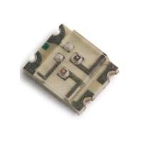
This is our 1.10mm Height 1210 Package Super Red and Yellow Green Bi-color (Multi-color) Chip LED. This 1210 Bi-color series are available many other Colors.

Features:
Descriptions:
Applications:
Package Dimension:

| Part No. | Chip Material | Lens Color | Source Color | |
| DL-PCB1210RGC-1R-1G | S | GaAlAs | Water Clear | Super Red |
| G | GaP | Yellow Green | ||
Notes:
Absolute Maximum Ratings at Ta=25℃
| Parameters | Symbol | Emitting Color | Max. | Unit |
| Power Dissipation | PD | Super Red | 60 | mW |
| Yellow Green | 72 | |||
Peak Forward Current (1/10 Duty Cycle, 0.1ms Pulse Width) | IFP | Super Red | 100 | mA |
| Yellow Green | 100 | |||
| Continuous Forward Current | IF | Super Red | 25 | mA |
| Yellow Green | 30 | |||
| Reverse Voltage | VR | 5 | V | |
| Electrostatic Discharge (HBM) | ESD | 2000 | V | |
| Operating Temperature Range | Topr | -40℃ to +80℃ | ||
| Storage Temperature Range | Tstg | -40℃ to +85℃ | ||
| Soldering Temperature | Tsld | 260℃ for 5 Seconds | ||
Electrical Optical Characteristics at Ta=25℃
| Parameters | Symbol | Emitting Color | Min. | Typ. | Max. | Unit | Test Condition |
| Luminous Intensity | IV | Super Red | 15 | 35 | --- | mcd | IF=20mA (Note 1) |
| Yellow Green | 16 | 30 | --- | ||||
| Viewing Angle | 2θ1/2 | Super Red | --- | 120 | --- | Deg | IF=20mA (Note 2) |
| Yellow Green | --- | 120 | --- | ||||
| Peak Emission Wavelength | λp | Super Red | --- | 660 | --- | nm | IF=20mA (Measurement @Peak) |
| Yellow Green | --- | 575 | --- | ||||
| Dominant Wavelength | λd | Super Red | --- | 640 | --- | nm | IF=20mA (Note 3) |
| Yellow Green | --- | 573 | --- | ||||
| Spectral Line Half-Width | △λ | Super Red | --- | 45 | --- | nm | IF=20mA |
| Yellow Green | --- | 30 | --- | ||||
| Forward Voltage | VF | Super Red | 1.80 | 2.20 | 2.80 | V | IF=20mA |
| Yellow Green | 1.80 | 2.20 | 2.80 | ||||
| Reverse Current | IR | Super Red | --- | --- | 10 | µA | VR=5V |
| Yellow Green |
Notes:
Typical Electrical / Optical Characteristics Curves
(25℃ Ambient Temperature Unless Otherwise Noted)
Super Red:

Yellow Green:

The reliability of products shall be satisfied with items listed below:
Confidence level: 90%.
LTPD: 10%.
1) Test Items and Results:
| No. | Test Item | Test Hours/Cycles | Test Conditions | Sample Size | Ac/Re |
| 1 | Resistance to Soldering Heat | 6 Min | Tsld=260±5℃, Min. 5sec | 25pcs | 0/1 |
| 2 | Thermal Shock | 300 Cycles | H: +100℃ 5min ∫ 10 sec L: -10℃ 5min | 25pcs | 0/1 |
| 3 | Temperature Cycle | 300 Cycles | H: +100℃ 15min ∫ 5min L: -40℃ 15min | 25pcs | 0/1 |
| 4 | High Temperature Storage | 1000Hrs. | Temp: 100℃ | 25pcs | 0/1 |
| 5 | DC Operating Life | 1000Hrs. | IF=20mA | 25pcs | 0/1 |
| 6 | Low Temperature Storage | 1000Hrs. | Temp: -40℃ | 25pcs | 0/1 |
| 7 | High Temperature/ High Humidity | 1000Hrs. | 85℃/85%RH | 25pcs | 0/1 |
2) Criteria for Judging the Damage:
| Item | Symbol | Test Conditions | Criteria for Judgment | |
| Min | Max | |||
| Forward Voltage | VF | IF=20mA | --- | F.V.*)×1.1 |
| Reverse Current | IR | VR=5V | --- | F.V.*)×2.0 |
| Luminous Intensity | IV | IF=20mA | F.V.*)×0.7 | --- |
*) F.V.: First Value.
Reel Dimensions:

Carrier Tape Dimensions:
Loaded quantity 2000PCS per reel.

Please read the following notes before using the product:
1. Over-current-proof
Customer must apply resistors for protection, otherwise slight voltage shift will cause big current change (Burn out will happen).
2. Storage
2.1 Do not open moisture proof bag before the products are ready to use.
2.2 Before opening the package, the LEDs should be kept at 30℃ or less and 90%RH or less.
2.3 The LEDs should be used within a year.
2.4 After opening the package, the LEDs should be kept at 30℃ or less and 70%RH or less.
2.5 The LEDs should be used within 168 hours (7 days) after opening the package.
2.6 If the moisture adsorbent material (silica gel) has fabled away or the LEDs have exceeded the storage time, baking treatment should be performed using the following conditions. Baking treatment: 60±5℃ for 24 hours.
3. Soldering Condition
3.1 Pb-free solder temperature profile.
3.2 Reflow soldering should not be done more than two times.
3.3 When soldering, do not put stress on the LEDs during heating.
3.4 After soldering, do not warp the circuit board.
4. Soldering Iron
Each terminal is to go to the tip of soldering iron temperature less than 260℃ for 5 seconds within once in less than the soldering iron capacity 25W. Leave two seconds and more intervals, and do soldering of each terminal. Be careful because the damage of the product is often started at the time of the hand solder.
5. Repairing
Repair should not be done after the LEDs have been soldered. When repairing is unavoidable, a double-head soldering iron should be used (as below figure). It should be confirmed beforehand whether the characteristics of the LEDs will or will not be damaged by repairing.
6. Caution in ESD
Static Electricity and surge damages the LED. It is recommended to use a wrist band or anti-electrostatic glove when handling the LED. All devices, equipment and machinery must be properly grounded.


