Introduction
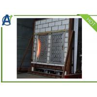
Fire resistance performance of material provide important
information for evaluation samples and Assembly properties. This
vertical fire resistance furnace is a quantitative method of
material vertical position and ability to withstand high
temperatures.This vertical furnaces can be used for evaluation of
fire resistant products, such as walls, doors, air dampers,
connections and infiltration sealing agent. Evaluation samples a
number of features, including load-carrying capacity, fire control,
heat transfer, and so on.
The vertical fire resistance test furnace is designed to comply
with the relevant parts of building materials in fire resistance
test of EN1363-1,1363-2 hydrocarbon curve and relevant requirements
of ISO standard834,and is similar to other States of the relevant
provisions. The machine is specifically designed and after years of
improvement, formed a kind of test specimens configuring reliable
and accurate methods and necessary part of the combustion chamber,
which can be placed on the combustion chamber contains samples of
various types of restrictive framework. The control at a specific
time, temperature and pressure conditions, the response to heating
of the sample to evaluate specific performance standards.
The furnace in the production and installation of lining and tested
in the factory, According to your preset function, disassemble into
parts packed into trailers suitable for heavy transport.
Structure:
• The inner space of this fire resistance test furnace is 3000mm
(w) x 3000mm (h) x 1300mm (d).
• Lined with 1400 class insulation bricks, refractory filling block
and the slag plate.furnace top laying with special-shaped brick and
lined with refractory material in situ.
• A non deformable gate is located on one end of the furnace wall,
which is fully lined with a hinge and clamping means to provide a
passageway into the furnace.
• In some regions apply diatomaceous earth insulation and the super
thermal insulation material at low temperature, in a hazardous area
area and base of the combustion chamber all for to cement the
connection as much as possible using the 42% dense alumina
refractory brick lining in the 6-hour high temperature during the
test will provide sufficient insulation.
• Able to carry out no load test on horizontal test samples fixed
on a custom frame.
• The structure is efficient and safe and the wall of furnace is
made of insulating firebrick, refractory pouring block and slag
plate made of refractory lining refractory insulating brick
noodles, along the wall lining with the hot surface, with high
temperature in situ block.
• Special-shaped brick used on top of Removable Pu and lined with
refractory material in situ.
• Furnace using low carbon steel, reinforced with c channel steel
and h-beams, steel resolve hot deformation.
• Sample fixed boxes mounted on the furnace front, fixed by four
sets of doors.
• Four observation port is located on the long side of the wall,
use a heat-resistant quartz glass, convenient operators watch the
whole sample in a test case.
• Air cooler insulating frame lightweight aluminum fiberboard
sliding doors without using a observation port, slide the door
blocking the oven available in the heat.
• Heat - resistant nozzle mix burners. The burner use liquefied
petroleum gas, equipped with flame monitoring device, to ensure the
safety of combustion at any time. Equipped with all fire safety
system, ignition system and continuous temperature sensor.
• Combustion control panel, automatic and manual mode can be used.
Use button switches at any time automatically inserted into the
mouth, according to the preset heat curve light burning mouth, such
as the BS 476-DI20-24bu, EN 1363 and IMO the hydrocarbon curve.
Manual control can be lit to specify burning mouth burning mouth.
• The three genuine leaks smoke cross section is circular, each of
which contains an airlock. These three air brakes is a round of
high-level stainless steel structure and its shaft water cooling.
Flue liner here for biodegradable ceramic fiber material.
• Furnace using low carbon steel, reinforced with c channel steel
and h-beams, solve the thermal deformation of the steel issue,
designed as a strong deformation structures. Strengthening plates
for burners, hole, thermocouples, pressure and monitoring points
provide holes. Steel frame is designed to ensure that you have
considered the use function. The durable nature of the equipment to
ensure its life expectancy in a test environment.
Main feature:
• In line with the latest regulations of the thermocouple, location
and design. Can provide the nine thermocouples in the posterior wall of the
furnace. Accessories in the packaging, we will supply the right
kind of nickel-iron alloy pipes, to support the delivery of the
thermocouple.
• In line with the latest regulations of pressure points, location
and design
Place 2 on each side of the combustion chamber wall of nickel-iron
alloy pipes, end of the tube "t" shape. Pressure points are all
connected to the field wiring of inverter.
• LP gas industrial high temperature light soft flame burner
Burner upright position, 6 on each side wall about burning mouth.
Burning mouth using LPG. Equipped with all fire safety systems,
intermittent ignition systems, and temperature sensors.
• Lifting frame and the fixed sample box
High temperature resistance of precast blocks arranged in a
stainless steel frame, high temperature and lining. These
frameworks are to be load-bearing framework. Another separate
lifting with two side hooks for lifting samples box to the furnace.
Horizontal sample frame can be easily sent into the furnace.
• Refractory lining of the connection pipe and chimney
The chimney is made of mild steel ,the former 6m with
heat-resistant inner lining. On top of the chimney into the furnace
high temperature at least 3 metres from the location, but also
according to the required specifications for design of chimney.
• Burner air intake fan
Combustion air system is pumping well before the current test.
• Temperature sensors and pressure gauge
Equipped with 9 K-type thermocouple, one flat type thermocouple, a
pressure gauge and a thermocouple at normal temperature for
assembly.
• Observation window
After four in the furnace wall, made of heat-resistant glass, air
cooled, connect the supply tubes and stainless steel insulated
thermal panels. Alternatives to the viewers is the aperture of the
camera.
• Motorized Pressure Controlled Dampers
Gas will go through three openings into the ducts to the furnace
back, then to theflue of a common ground. The three air brake is
driven by the motor,control the pressure of combustion chamber .
The air brake has to be cooled by water and it requires customers
to provide water and drainage.
• Electrical installation
All solenoid valves, safe box, spark plugs, fire detectors, vacuum
and overpressure switch, electric valves and lock in the security
limit switch will be made to connect field wiring terminal junction
box by the installation engineer.
• PLC and computer control
PLC systems formed by Siemens PLC CPU and SIEMENS Compatible Remote
I/O. Fire data management software is written according to
customer's requirements to collect and store test data.It meets BS
476 part 20-24, EN 1363 and IMO hydrocarbon curve heating
requirements. Other standardtime temperaturecurves can also be
programmed into the system in advance. The PLC controller includes
a built-in operating interface, including the required recording
and programming capabilities, as well as the necessary motor
starter for all systems. The system programming can heat the curve
in thereal timeand shows the boiler control system on computer
screen.
• Data recording system with dual recording
Record the data on the computer and during the test period, it
displays thereal timeanalysis data of the test samples. The device
can spread its screen display on a standard computer network and
any computer connected to the network can log in to the test
information. The facility can be used to provide test data to
observers in the laboratory. All records are automatically saved to
another computer.
• Manual control
The Test Furnace can be operated manually. The complete ignition system is not in
any way dependent on the operation of the control computer. Press
the clear start button to light the stove. A series of light
instructions to clear the sequence correctly. Once they are on a
separate burner Control Panel lighting up all the available at the
pre-set time burner. If the furnace is not lit during that period,
the system will have to be removed. Each region of the position of
the air and gas damper motor can be adjusted individually or by a
group of the main control regulation. During the test, the safety
of the furnace is monitored by a set of interlocking devices, each
of which has its own indicator light. The interlocking devices are
closed, so that the linkage of the furnace closure is captured and
maintained to the manual reset ignition sequence and an audible
alarm device installed.
Technical specifications:
| 1 | Channel | a total of 240,bipolar difference |
| 2 | Connector | 4 mm round socket (per channel 2). Other types of requirements are
available |
| 3 | Input range | DC voltage of 5 mv , 50mv , 500 mv, 5000mv (software programmable) |
| 4 | Basic resolution | 21 bit |
| 5 | Basic accuracy | 0.005%FS |
| 6 | Measuring speed | 1 ms to 3 seconds (software programmable) |
| 7 | Cold-junction compensation | Absolute compensation +0.1ºC |
| 8 | Computer interface | RS485 75 ohm twisted pair |
| 9 | Power supply | 200-240 VAC or 100 -130VAC or 24VAC 40 -70Hz |
| 10 | Power consumption | 7VA |