

Active Member
|
[China]

Address: Room 301, Building No.1, No. 2 Jiaolian Yiheng Rd, Wanjiang District, Dongguan, China, 523046
Contact name:Raymond Chung

Dongguan Quality Control Technology Co., Ltd. |
|
|
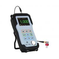
Echo Mode Ultrasonic Thickness Gauge with OLED Screen and Resolution 0.001mm
Characteristics:
1. High precision, 0.001mm resolution;
2. Real time A-Scan with adjustable gain, range, blanking etc;
3. Especially fits for ultra-thin work-piece, can accurately and
reliably measure down to 0.2 mm;
4. Measure through coatings, e.g. coatings on the substrate, the
net thickness of the substrate can be
measured without removing coatings;
5. Unique multiple-wave verify mode, all the thickness values have
been checked through 3 to 9 times
of echos, which makes the result more reliable and accurate.
Technical Data:
| Display | 2.4QVGA(320×240)true color OLED screen, contrast 10000:1 |
| Measuring Modes | Interface-Echo Mode( I-E): for thick material |
| Echo-Echo Mode (E-E): for the thin material and measure through the coating | |
| Multiple Echo Verify Mode (ME-E): All the thickness values have been checked through 3 to 9 times of echos, which makes the result more reliable and accurate | |
| Auto Mode:The instrument select the measuring mode automatically according to the different material being tested | |
| Measuring Range( Steel) | Interface-Echo Mode: 1.5mm-27mm |
| Echo-Echo Mode: 0.25mm-13.5mm | |
| Multiple Echo Verify Mode: 0.25mm-9mm | |
| Auto Mode: 0.25mm-27mm | |
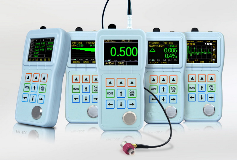
| Display Mode | A-SCAN: Displays the whole RF echo or half-waveform after rectified |
| B-SCAN: Real time B-Scan, displays the profile of the work-piece | |
| Big Thickness Value: The conventional display of the thickness value | |
| Difference/Thickness thinning rate: Display the difference between the real thickness value and the preset thickness value, and the percentage of the thinning value | |
| Min./Max. Capture: Display the current thickness value, Min. value and Max. value at the same time | |
| Gain | Real time continuously adjustable, adjustable range 41dB |
| Measuring Resolution | 0.001 mm or 0.01mm (0.0001in or 0.001in) |
| Material Velocity Range | 500-9999m/s, 0.0197-0.3937inch/microsecond |
| Alarm Setting | Dynamically change the color of thickness value when the measuring value exceeds the upper limit or lower limit of preset |
| Units | Inch or Millimeter |
| Language | Chinese, English, French, Germany, Japanese |
| Power | 2 AA size batteries, Operating time is more than 35 hours |
| Instrument Shut-off | Select ALWAYS ON or AUTO OFF after 5, 10 or 20 minutes of inactivity |
| Working Temperature | -10℃ ~+50℃ |
| Size | 153mm × 76mm ×37mm(H ×W ×D) |
| Weight | 280g including batteries |
| Data Recorder | |
| Capacity | 400 Files, 100,000 Thickness Values and 1000 Groups of Wave forms |
| File Structure | Grid File |
| Line Number * Column Number | 21*12 |
| Communication Connector | USB 2.0 Full Speed Connector |
| Communication Software | Data View Software |
Standard Delivery:
| Ultrasonic Thickness Gauge | 1 |
| Probe | 1 |
| Probe Cable | 1 |
| Communication Cable | 1 |
| Instrument Case | 1 |
| Coupling Agent (take off ship by air) | 1 |
| Battery (take off ship by air) | 2 |
| Data Communication Software | 1 |
| User Manual, Packing List, Warranty Card | 1 |
In any ultrasonic gaging application, the choice of gage and
transducer will depend on the material to be measured, thickness
range, geometry, temperature, accuracy requirements, and any
special conditions that may be present. Olympus NDT can provide
full details for specific applications. Listed below are the major
factors that should be considered.
Material: The type of material and the range of thickness being measured are
the most important factors in selecting a gage and transducer. Many
common engineering materials including most metals, ceramics, and
glass transmit ultrasound very efficiently and can easily be
measured across a wide thickness range. Most plastics absorb
ultrasonic energy more quickly and thus have a more limited maximum
thickness range, but can still be measured easily in most
manufacturing situations. Rubber, fiberglass, and many composites
can be much more attenuating and often require high penetration
gages with pulser/receivers optimized for low frequency operation.
Thickness: Thickness ranges will also dictate the type of gage and transducer
that should be selected. In general, thin material are measured at
high frequencies and thick or attenuating materials are measured at
low frequencies. Delay line transducers are often used on very thin
materials, although delay line (and immersion) transducers will
have a more restricted maximum measurable thickness due to
potential interference from a multiple of the interface echo. In
some cases involving broad thickness ranges and/or multiple
materials, more than one transducer type may be required.
Geometry: As the surface curvature of a part increases, the coupling
efficiency between the transducer and the test piece is reduced, so
as radius of curvature decreases the size of the transducer should
generally be decreased as well. Measurement on very sharp radiuses,
particularly concave curves, may require specially contoured delay
line transducers or non-contact immersion transducers for proper
sound coupling. Delay line and immersion transducers may also be
used for measurement in grooves, cavities and similar areas with
restricted access.
Temperature: Common contact transducers can generally be used on surfaces up to
approximately 125° F or 50° C. Use of most contact transducers on
hotter materials can result in permanent damage due to thermal
expansion effects. In such cases, delay line transducers with
heat-resistant delay lines, immersion transducers, or high
temperature dual element transducers should always be used.
Phase Reversal: There are occasional applications where a material of low acoustic
impedance (density multiplied by sound velocity) is bonded to a
material of higher acoustic impedance. Typical examples include
plastic, rubber, and glass coatings on steel or other metals, and
polymer coatings on fiberglass. In these cases the echo from the
boundary between the two materials will be phase reversed or
inverted with respect to the echo obtained from an air boundary.
This condition can normally be accommodated by a simple setup
change in the instrument, but if it is not taken into account,
readings may be inaccurate.
Accuracy: Many factors affect measurement accuracy in a given application,
including proper instrument calibration, uniformity of material
sound velocity, sound attenuation and scattering, surface
roughness, curvature, poor sound coupling, and backwall
non-parallelism. All of these factors should be considered when
selected a gage and transducer. With proper calibration,
measurements can usually be made to an accuracy of +/- 0.001" or
0.01 mm, and in some cases accuracy can approach 0.0001" or 0.001
mm. Accuracy in a given application can best be determined through
the use of reference standards of precisely known thickness. In
general, gages using delay line or immersion transducers for Mode 3
measurements are able to determine the thickness of a part most
precisely.


