Industrial Servo Motor Yakasawa Electric SGM-02A314B Motor
AC. Servo 2.0A 3000r/min
Specifications
Manufacturer: Yaskawa
Product number: SGM-02A314B
Description: SGM-02A314B is an Motors-AC Servo manufactured by Yaskawa
Servomotor Type: SGM
Rated Output: 200W (0.25HP)
Power Supply: 200V Standard
Encoder Specifications: 2048 P/R Incremental Encoder
Revision Level: Standard or CE Specification
Shaft Specifications: Straight with keyway
Options: 90VDC Brake

SIMILAR PRODUCTS
SGM-01AW14B
SGM-02A314B
SGM-02L3B4L
SGM-02U3B4L
SGM-04A314B
SGM-04U3B4L
SGM-08U3B4L
SGM-A3U3B4L
SGM-A3L314P
SGM-A3L3B2L
SGM-A3LW14P
SGM-A3V314B
SGM-A3BW14P
SGM-A5U3B4L
SGM-A5A314S
SGM-01U3B4L
SGM-01U3B4CL
SGM-01L314P
SGM-01L3B2L
SGM-01L3B4L
Cable Length between Drive and Motor The E7 should be installed as
close as possible to the motor to minimize the length of load side
power cable needed between the Drive and the motor. If the cable
between the Drive and the motor is long, the high-frequency leakage
current will increase, causing the Drive output current to increase
as well. This may affect peripheral devices. To prevent this,
reduce the cable length whenever possible, or if necessary, adjust
the carrier frequency (set in C6-02) as shown in Table 2.6. The
line side power cables, load side power cables and the control
wiring should all be run in a separate conduit. Careful attention
to this recommended design practice will avoid many potential motor
and Drive related problems.
Ground Wiring Observe the following precautions when connecting
the ground wire: 1. 208-240Vac Drives should have a ground
connection with resistance of less than 100Ω. 2. 480Vac Drives
should have a ground connection with resistance of less than 10Ω.
3. Do not share the ground wire with other devices, such as motors
or large-current electrical equipment. 4. Always use a ground wire
that complies with technical standards on electrical equipment and
minimize the length of the ground wire. Leakage current flows
through the Drive. Therefore, if the distance between the ground
rod and the ground terminal is too long, potential on the ground
terminal of the Drive will become unstable. 5. When using more than
one Drive, be careful not to loop the ground wire. See Fig 2.4.
Control Circuit Ground Terminals The removable Drive control
terminal card provides two ground terminals (marked TB3 and TB4) to
accept the control wire shield connection. The control wire shield
should be connected on this end only, the opposite end should be
isolated with electrical tape.
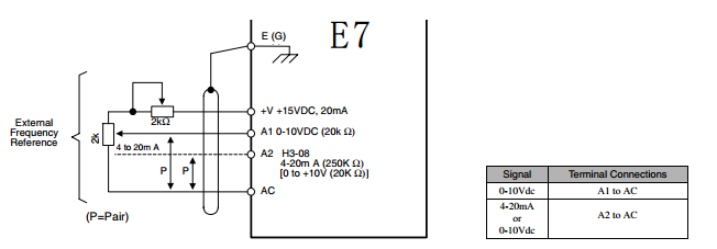
Control Circuit Wire Sizes The auto mode speed reference (speed
command) field wiring connection is made to E7 Drive terminals A1
or A2 (signal positive), AC (signal common) and G (shield). Keep
this lead length as short as possible to maintain signal quality.
Insulated twisted shielded pair wire (2 conductor # 18 ga, Belden
8760 or equivalent) is required. Do not run these wires in the same
conduit as other AC power or control wires. The shield must be
connected on this end only, stub and isolate the other end. The A2
signal employed is 4 to 20 mA with parameter H3-08 set for “2: 4 -
20 mA”. For 0 to 10 VDC, parameter H3-08 is set for “0: 0 - 10 VDC”
and the E7 control board DIP switch S1-2 must be in the OFF
position. (See Fig 2.4). For remote operation, keep the length of
the control wiring to 50m or less. Separate the control wiring from
high-power lines (input power, motor leads or relay sequence
circuits) to reduce noise induction from peripheral devices. When
setting speed commands (frequency references) from an external
speed potentiometer (and not from the Digital Operator), use
shielded twisted-pair wires and ground the shield to terminal E(G),
as shown in Fig 2.3. Terminal numbers and wire sizes are shown in
Table 2.7.
OTHER SUPERIOR PRODUCTS
| Yasakawa Motor, Driver SG- | Mitsubishi Motor HC-,HA- |
| Westinghouse Modules 1C-,5X- | Emerson VE-,KJ- |
| Honeywell TC-,TK- | GE Modules IC - |
| Fanuc motor A0- | Yokogawa transmitter EJA- |
Contact person: Anna
E-mail: wisdomlongkeji@163.com
Cellphone: +0086-13534205279