

Active Member
|
[China]

Address: No.116.Chengyang Road, Xiangcheng district , Suzhou , China.
Contact name:LV

oepoch industrial technology |
|
|
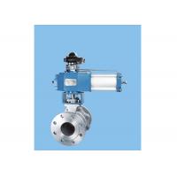
RB series O type ball valve
It is a right angle rotary type shut-off valve.It is used with pneumatic actuators or electric actuators to achieve remote shut-off control or manual control with a wrench or handwheel. The structure adopts a movable seal to make a two-way seal design. It has large shearing force and self-cleaning function when there is no gap between the two-way sealing valve seat, especially suitable for controlling the suspension with fibers and fine solid particles or viscous media on and off. Therefore, this product is widely used in the automatic control systems of chemical, biochemical, petrochemical, polycrystalline, environmental, pharmaceutical, light industry, paper and other industrial sectors.
Design Featur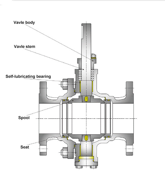
Valve body
The valve body adopts a diameter design and has a small flow resistance.
Valve stem
The outer circle is made of coreless grinding, and the friction coefficient between the filler and the packing is small. The friction loss is minimized, and the valve opening and closing torque is greatly reduced.
Self-lubricating bearing
The upper and lower stems are fixed with double bearings for extremely high rotation accuracy and rotational stability. The bearing is made of a special process of sintering copper on a stainless steel surface and then rolling PTFE on the copper surface. It has excellent wear resistance and self-lubricating function, which avoids the valve stem and bearing seizure phenomenon in the long-term use of the valve.
Spool
The fixed valve core design has small opening and closing torque, flexible opening and stable operation.
Seat
The metal sealing ball valve adopts a two-way metal movable sealing structure, which adds a pre-tightening spring with automatic compensation and self-cleaning function. Because of the two-way seal, the valve body is installed without regard to the flow direction of the medium.
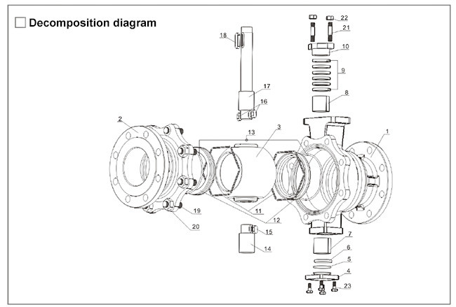
Parts List
| Nunber | Name | Quantity(Piece) | Material |
| 1 | Upper valve body | 1 | WCB,CF8,CF8M |
| 2 | Lower valve body | 1 | WCB,CF8,CF8M |
| 3 | Spool | 1 | CF8,CF8M+Hard chromium plating or spray welding Stelle |
| 4 | Gland | 1 | WCB,CF8,CF8M |
| 5 | O-ring | 1 | Fluororubber |
| 6 | Pad | 1 | PTFE |
| 7 | Self-lubricating bearing | 1 | Composite material |
| 8 | Self-lubricating bearing | 1 | Composite material |
| 9 | V type packing | A group | PTFE |
| 10 | Gland | 1 | CF8 |
| 11 | Preload spring | 2 | SS316 |
| 12 | Movable seal seat | 2 | SS304,SS316+Hard chromium plating or spray welding Stelle |
| 13 | O-ring | 2 | Fluororubber |
| 14 | Lower stem | 1 | 17-4PH SS316 |
| 15 | Flat key | 1 | SS304,SS316 |
| 16 | Flat key | 2 | SS304,SS316 |
| 17 | Upper stem | 1 | 17-4PH SS316 |
| 18 | Flat key | 1 | SS304 |
| 19 | Stud | On demand | SS304 |
| 20 | Hex nuts | On demand | SS304 |
| 21 | Stud | 2 | SS304 |
| 22 | Hex nuts | 2 | SS304 |
| 23 | Hex Bolts | 4 | SS304 |
Technical Parameters
Nominal diameter (DN) :15,20,25,32,40,50,65,80,100,125,150,200,300,450,500.
Nominal pressure (PN): 1.0,1.6,2.5,4.0,6.4(Mpa)ASME150,300LB
Connection form: flange type.
Temperature range: -40~160 (normal temperature); -40~230 (medium temperature); -40~425 (high temperature)
Pressure test: Each valve is tested for shell strength and sealing performance. The shell test pressure is 1.5 times the nominal pressure. The seal test is 1.1 times the nominal pressure. The test medium is water.
Flow characteristics: The flow characteristics of the O-type fixed shut-off ball valve are fast opening characteristics.
Leakage: Metal-sealed seat media tested in the direction of the arrow to meet Class F of the ISO5208 seal rating, equivalent to the ANSI/FCI0.2IV x 1/100 standard. See the table below for details.
Maximum allowable leakage
| DN(mm) | Metal seat | Soft seat |
| 25 | 1.5ml/min | 0.15ml/min |
| 32 | 1.9ml/min | 0.19ml/min |
| 40 | 2.4ml/min | 0.24ml/min |
| 50 | 3.0ml/min | 0.30ml/min |
| 65 | 3.9ml/min | 0.39ml/min |
| 80 | 4.8ml/min | 0.48ml/min |
| 100 | 6.0ml/min | 0.60ml/min |
| 125 | 7.5ml/min | 0.75ml/min |
| 150 | 9.0ml/min | 0.90ml/min |
| 200 | 12.0ml/min | 1.20ml/min |
| 250 | 15.0ml/min | 1.50ml/min |
| 300 | 18.0ml/min | 1.80ml/min |
| 350 | 21.0ml/min | 2.10ml/min |
| 400 | 24.0ml/min | 2.40ml/min |
| 450 | 27.0ml/min | 2.70ml/min |
| 500 | 30.0ml/min | 3.00ml/min |
Actuator configuration table
| diameter | Calculated torque | Z series actuator | Fine actuator | Air pressure | ||||
| (mm) | (1.6MPa) | ZSQ double acting actuator | ZDQ single acting actuator | DA(Double acting) | SR(single acting) | Electric | (MPa) | |
| 25 | 25 | ZSQ32-φ63-φ16 | ZDQ41-φ100-φ16 | 63 | 85 | 10 | 0.5~0.7 | |
| 32 | 30 | ZSQ32-φ63-φ16 | ZDQ41-φ100-φ16 | 63 | 100 | 10 | ||
| 40 | 35 | ZSQ41-φ80-φ16 | ZDQ41-φ100-φ16 | 75 | 100 | 10 | ||
| 50 | 45 | ZSQ41-φ80-φ20 | ZDQ41-φ125-φ20 | 85 | 115 | 10 | ||
| 65 | 65 | ZSQ41-φ100-φ20 | ZDQ41-φ125-φ20 | 100 | 115 | 10 | ||
| 80 | 100 | ZSQ50-φ100-φ25 | ZDQ50-φ125-φ25 | 100 | 160 | 20 | ||
| 100 | 150 | ZSQ50-φ100-φ30 | ZDQ60-φ160-φ30 | 125 | 160 | 20 | ||
| 125 | 250 | ZSQ50-φ125-φ30 | ZDQ60-φ200-φ30 | 125 | 200 | 40 | ||
| 150 | 350 | ZSQ60-φ125-φ40 | ZDQ80-φ200-φ40 | 140 | 200 | 40 | ||
| 200 | 640 | ZSQ60-φ160-φ40 | ZDQ80-φ250-φ40 | 160 | 240 | 60 | ||
| 250 | 1200 | ZSQ80-φ200-φ45 | ZDQ100-φ300-φ45 | 210 | 300 | 100 | ||
| 300 | 1700 | ZSQ80-φ250-φ50 | ZDQ130-φ350-φ50 | 240 | 350 | |||
| 350 | 2300 | ZSQ100-φ300-φ60 | ZDQ130-φ400-φ60 | 270 | 400 | |||
| 400 | 3500 | ZSQ130-φ300-φ70 | ZDQ160-φ400-φ70 | 300 | 500 | |||
| 450 | 4500 | ZSQ130-φ350-φ80 | ZDQ160-φ450-φ80 | 350 | 500 | |||
Note: The ZSQ and ZDQ actuators are developed by our company. See the Z series actuator samples for details. The above valve actuator is configured to have a nominal valve pressure of 1.6 MPa at normal temperature, and a pneumatic actuator with a source pressure of 0.5 MPa is recommended. If the valve nominal pressure is greater than 1.6MPa, the actuator configuration will be recommended separately.
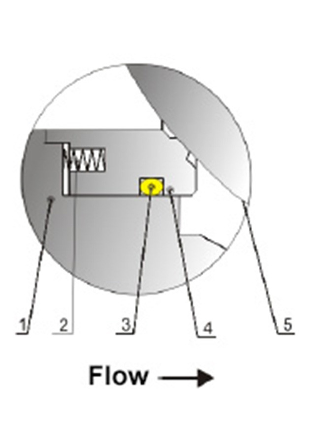
Valve seat seal structure
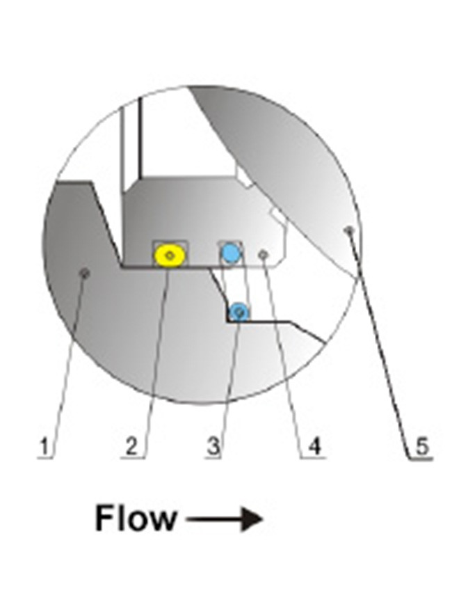
Metal sealing seat (DN≤300)
| No. | Item | Temperature℃ |
| 1 | Vavle body | -40℃~120℃ -40℃~230℃ |
| 2 | O ring | |
| 3 | Seal seat spring | |
| 4 | Vavle seat | |
| 5 | Spool |
Metal sealing seat (DN≤300)
| No. | Item | Temperature℃ |
| 1 | Vavle body | -40℃~120℃ -40℃~230℃ |
| 2 | O ring | |
| 3 | Seal seat spring | |
| 4 | Vavle seat | |
| 5 | Spool |
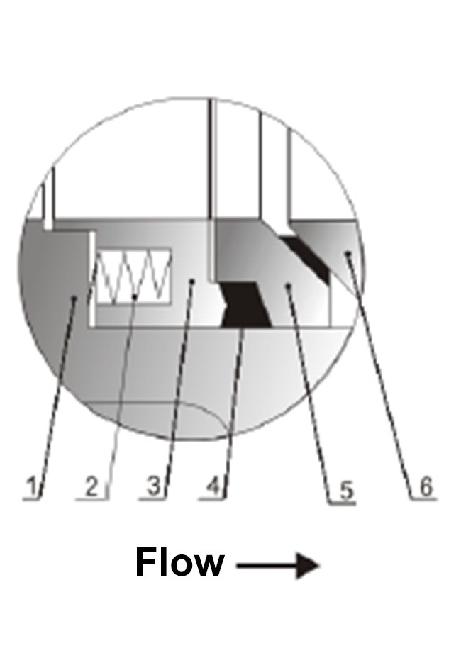
High temperature metal sealing seat
| No. | Item | Temperature℃ |
| 1 | Vavle body | -40℃~425℃ |
| 2 | Cylindrical spring | |
| 3 | Pressure ring | |
| 4 | Graphite ring | |
| 5 | Vavle seat | |
| 6 | Spool |
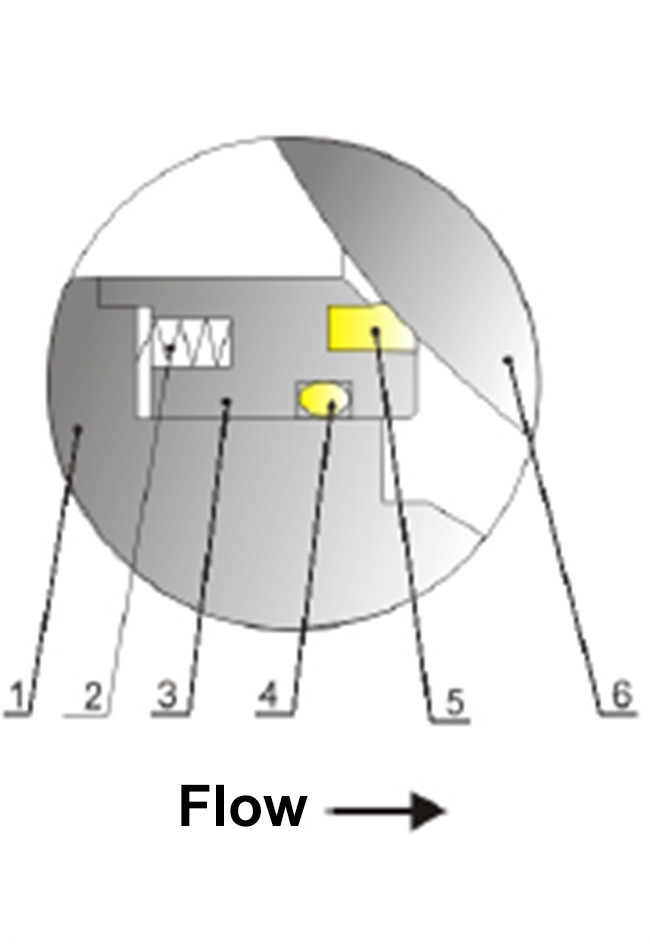
Soft sealing seat
| No. | Item | Temperature ℃ |
| 1 | Vavle body | -40℃~160℃ |
| 2 | Cylindrical spring | |
| 3 | Pressure ring | |
| 4 | Graphite ring | |
| 5 | Vavle seat | |
| 6 | Spool |
Application
Pulp and fiber control in the paper industry
Slurry control in the biochemical industry
Powder and hard particle fluid control
Various flow control and pressure control
Flanged O-ring ball valve size chart(mm)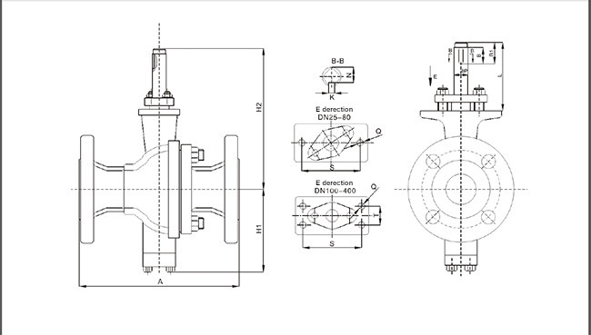
| DN | Dimensions | Connection size | reference weight | ||||||||||
| mm | A | H1 | H2 | L | B | B1 | K | N | φP | Q | S | T | (kg) |
| 25 | 170 | 90 | 202 | 116 | 35 | 50 | 5 | 13 | 16 | M10 | 65 | / | 7.1 |
| 32 | 170 | 94 | 205 | 115 | 35 | 50 | 5 | 13 | 16 | M10 | 65 | / | 10 |
| 40 | 170 | 97 | 209 | 116 | 35 | 50 | 5 | 13 | 16 | M10 | 65 | / | 11 |
| 50 | 178 | 112 | 233 | 125 | 35 | 50 | 6 | 16.5 | 20 | M12 | 80 | / | 13 |
| 65 | 220 | 124 | 248 | 128 | 35 | 50 | 6 | 16.5 | 20 | M12 | 80 | / | 18.5 |
| 80 | 250 | 130 | 260 | 130 | 35 | 50 | 8 | 21 | 25 | M12 | 75 | / | 25 |
| 100 | 280 | 156 | 295 | 132 | 40 | 50 | 10 | 25 | 30 | M10 | 90 | 40 | 31 |
| 125 | 320 | 173 | 313 | 133 | 40 | 55 | 10 | 25 | 30 | M10 | 90 | 40 | 44 |
| 150 | 350 | 209 | 370 | 139 | 50 | 65 | 12 | 35 | 40 | M12 | 110 | 50 | 61 |
| 200 | 396 | 244 | 405 | 155 | 50 | 65 | 12 | 35 | 40 | M12 | 110 | 50 | 98 |
| 250 | 530 | 293 | 495 | 190 | 60 | 75 | 14 | 39.5 | 45 | M16 | 134 | 64 | 160 |
| 300 | 600 | 275 | 539 | 210 | 60 | 75 | 16 | 44 | 50 | M16 | 134 | 64 | 313 |
| 350 | 670 | 397 | 650 | 243 | 80 | 100 | 18 | 53 | 60 | M20 | 175 | 70 | 450 |
| 400 | 680 | 448 | 705 | 257 | 80 | 100 | 20 | 62.5 | 70 | M20 | 215 | 96 | 620 |
Note: The connection size in the above figure is the standard connection size of our Z series actuator.
Pneumatic flange type O-ring ball valve size chart (mm)
Code DN | A | H1 | H | G | F |
| 25 | 170 | 90 | 520 | 235 | 345 |
| 32 | 170 | 94 | 525 | 235 | 345 |
| 40 | 170 | 97 | 530 | 300 | 422 |
| 50 | 178 | 112 | 530 | 300 | 422 |
| 65 | 220 | 124 | 575 | 315 | 440 |
| 80 | 250 | 130 | 600 | 328 | 474 |
| 100 | 280 | 156 | 640 | 328 | 474 |
| 125 | 320 | 173 | 780 | 328 | 474 |
| 150 | 350 | 209 | 855 | 356 | 530 |
| 200 | 396 | 245 | 915 | 396 | 570 |
| 250 | 530 | 293 | 1180 | 500 | 700 |
| 300 | 600 | 375 | 1280 | 500 | 700 |
| 350 | 670 | 397 | 1370 | 571 | 844 |
| 400 | 680 | 448 | 1473 | 750 | 1050 |
| 450 | 750 | 490 | 1560 | 813 | 1258 |
| 500 | 914 | 510 | 1680 | 813 | 1258 |
Note: The above valve size is matched with a double-acting ZSQ actuator.
Code DN | A | H1 | H | G | F |
| 25 | 170 | 90 | 555 | 480 | 635 |
| 32 | 170 | 94 | 555 | 480 | 635 |
| 40 | 170 | 97 | 605 | 480 | 635 |
| 50 | 178 | 112 | 625 | 550 | 720 |
| 65 | 220 | 124 | 640 | 620 | 770 |
| 80 | 250 | 130 | 645 | 660 | 810 |
| 100 | 280 | 156 | 700 | 660 | 810 |
| 125 | 320 | 173 | 700 | 640 | 830 |
| 150 | 350 | 209 | 870 | 680 | 870 |
| 200 | 396 | 245 | 980 | 875 | 1170 |
| 250 | 530 | 293 | 1125 | 970 | 1260 |
| 300 | 600 | 375 | 1250 | 1200 | 1600 |
| 350 | 670 | 397 | 1215 | 1215 | 1615 |
| 400 | 680 | 448 | 1270 | 1270 | 1660 |
| 450 | 750 | 490 | 1285 | 1285 | 1680 |
| 500 | 914 | 510 | 1285 | 1285 | 1680 |
Note: The above valve size is a single-acting ZDQ actuator.
Pneumatic flange type O-ball valve size chart(mm)
Code DN | A | H1 | H | F |
| 25 | 170 | 90 | 555 | 178 |
| 32 | 170 | 94 | 555 | 178 |
| 40 | 170 | 97 | 600 | 178 |
| 50 | 178 | 112 | 630 | 214 |
| 65 | 220 | 124 | 650 | 246 |
| 80 | 250 | 130 | 680 | 295 |
| 100 | 280 | 156 | 710 | 340 |
| 125 | 320 | 173 | 760 | 398 |
| 150 | 350 | 209 | 820 | 478 |
| 200 | 396 | 245 | 935 | 562 |
| 250 | 530 | 293 | 1110 | 724 |
| 300 | 600 | 375 | 1280 | 928 |
| 350 | 670 | 397 | 1450 | 1300 |
Note: The above valve size is a double acting small DA actuator.
Electric flange type O-type ball valve size chart(mm)
Code DN | A | H1 | H | F | G |
| 25 | 170 | 90 | 390 | 157 | 140 |
| 32 | 170 | 94 | 432 | 207 | 147 |
| 40 | 170 | 97 | 440 | 207 | 147 |
| 50 | 178 | 112 | 450 | 207 | 147 |
| 65 | 220 | 124 | 490 | 256 | 182 |
| 80 | 250 | 130 | 500 | 256 | 182 |
| 100 | 280 | 156 | 588 | 256 | 182 |
| 125 | 320 | 173 | 632 | 256 | 182 |
| 150 | 350 | 209 | 705 | 256 | 182 |
| 200 | 396 | 245 | 815 | 380 | 240 |
| 250 | 530 | 293 | 920 | 380 | 240 |
| 300 | 600 | 375 | 1025 | 380 | 240 |
| 350 | 670 | 397 | 1125 | 380 | 240 |
Note: The above valve size is an electric actuator.
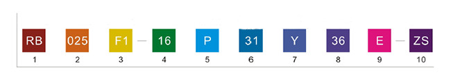
Model description
1.Valve type
| O-ball valve |
2. Nominal diameter
| GB/American Standard Series | ||
| 015 DN15 1/2″ | 080 DN80 2″ | 350 DN350 14″ |
| 020 DN20 3/4″ | 100 DN100 3″ | 400 DN400 16″ |
| 025 DN25 1″ | 125 DN125 5″ | 450 DN450 18″ |
| 032 DN32 1-1/4″ | 150 DN150 6″ | 500 DN500 20″ |
| 040 DN40 1-1/2″ | 200 DN200 8″ | |
| 050 DN50 2″ | 250 DN250 10″ | |
| 065 DN65 1-1/2″ | 300 DN300 12″ | |
3. Connection method
| F1 Flange type (RF side) | F2 Flange type (MF side) |
4. Nominal pressure, pound
| GB series | American standard series | Japanese standard series |
| 10 PN10 | 01 150LB | 1K 10K |
| 16 PN16 | 03 300LB | 2K 20K |
| 25 PN25 | ||
| 40 PN40 | ||
| 64 PN64 |
5. Body material
| Material | |||
| C | WCB | G | CG8M |
| P | CF8 | B | LCB |
| Q | CF3 | D | LCC |
| M | CF8M | W | WC6 |
| L | CF3M | ||
6. Spool material and surface treatment
| Spool material | Surface treatment | ||
| 1 | WCB/A105 | 0 | Polishing |
| 2 | F6a | 1 | Chrome |
| 3 | CF8/F304 | 2 | Nickel plating(ENP) |
| 4 | CF3/F304L | 3 | Spraying nickel-based alloy |
| 5 | CF8M/F316 | 4 | Spray welding tungsten carbide |
| 6 | CF3M/F316L | 5 | Ion nitridation |
| 7 | CG8M/F317 | 6 | Spray-welded Stilerite Alloy |
| B | 6AB(Spray super stainless steel) |
7. Seat seal form
| Ordinary hard seal | Y |
| High temperature structural hard seal | G |
| Soft seal | R |
8. Seat material and surface treatment
| Hard seal | Soft seal | |||
| Seat material | surface treatment | Material | ||
| 3 304 | 0 | Polishing | PO | PTFE |
| 4 304L | 1 | Chrome | RO | PTFE |
| 5 316 | 3 | Spraying nickel-based alloy | NO | NYLON |
| 6 316L | 4 | Spray welding tungsten carbide | LO | PPL |
| 7 317 | 5 | Ion nitridation | KO | PEEK |
| 6 | Spray-welded Stilerite Alloy | |||
9. O-ring material
| Material and operating temperature | ||
| E | EPDM | operating temperature -29℃~120℃ |
| V | VITON | operating temperature -29℃~200℃ |
| A | PFA | operating temperature -40℃~230℃ |
| F | FEP | operating temperature -40℃~160℃ |
| G | Graphite ring(High temperature structure) | operating temperature -40℃~425℃ |
10. Drive mode
| ZS | Pneumatic double acting |
| ZDK | Pneumatic single acting air opening |
| ZDB | Pneumatic single acting air closing |
| ZK | Electric |
| SD | Manual |


