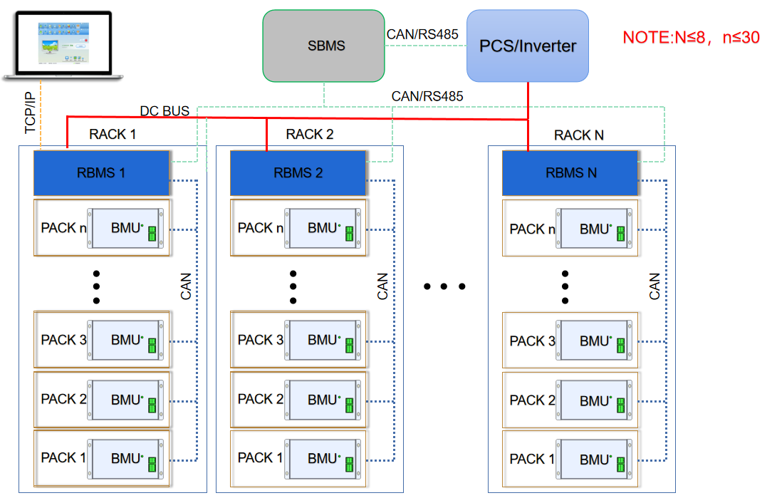
Communication protocol : Rs485,CAN, LAN
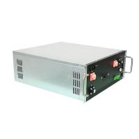
* 4U standard 19inch case
* Efficient, stable and reliable
* size:W485*H180*D550mm

|
|
[China]

Trade Verify
Address: Room 303, Building 6, Central Zhigu Phase I, No. 189, Section 2, Renmin East Road, Changsha Area, China (Hunan) Pilot Free Trade Zone
Contact name:Jeffrey

Hunan GCE Technology Co.,Ltd |
|
Verified Suppliers
|
|
|
Description
The primary function of a BMS is to ensure that the battery operates within safe limits and to maximize its performance and lifespan. This is achieved by monitoring key parameters such as voltage, current, temperature, and state of charge, and taking appropriate actions to prevent overcharging, overdischarging, or overheating.