Active Member
|
[China]

Address: Golden Bay Industrial Zone,Dongjiang Town, Binhu District, Wuxi City, Jiangsu Province,
Contact name:liuhongmao

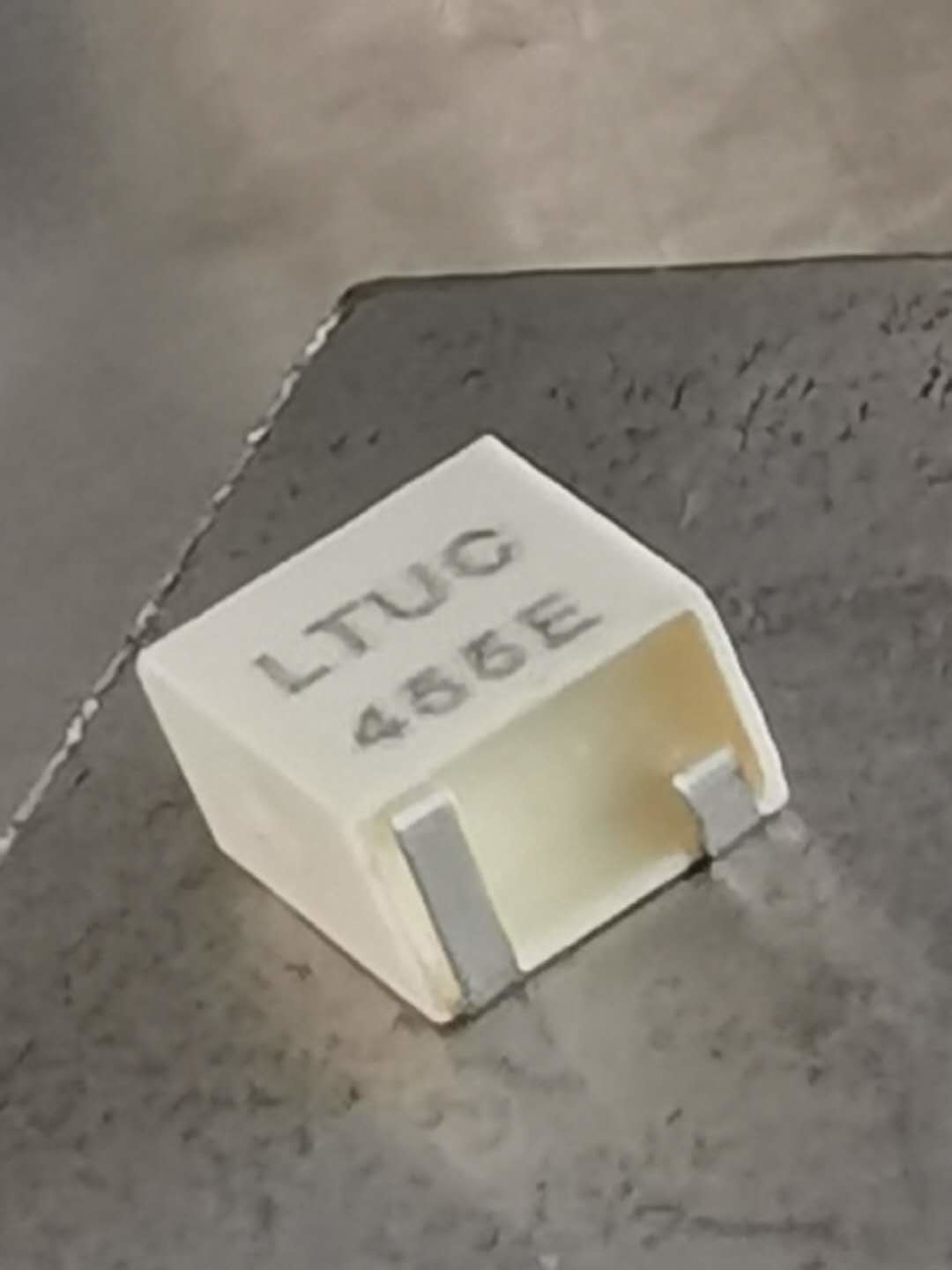
hanse-john electronic Co.,Ltd. |
|
|
| NO. | Item | Specification |
| 4 – 1 |
Center Frequency f0 (Center of 6dB Bandwidth) | 450±1.0 KHz |
| 4 – 2 | Bandwidth(3dB) | ±4.5KHz min |
| Bandwidth(6dB) | ±6.0KHz min | |
| Bandwidth(40dB) | ±12.5KHz min | |
| 4 – 3 | Stop Band Attenuation | 50dB min |
| 4 – 4 | Ripple (f0±5khz) | 1.0dB max |
| 4 – 5 |
Insertion Loss (At minimum loss point) | 4.0dB max |
| 4 – 6 | Temperature Stability (-20℃~ +80℃ ) | ±0.5% max (-25℃ ~ +80℃) |
| 4-7 | (0.1~1MHz)Spurious Response | 20dB min |
| 4-8 | (fo±2.0 kHz)GDT Ripple deviation | NO |
| 4-9 | Operating Temperature | -20℃ ~ +80℃ |
| 4-10 | Storage Temperature | -40℃ ~ +85℃ |
| 4-11 | Insulation Resistance(DC 25V 1 minute) | 100MΩ min |
| 4 – 12 | Input/Output Impedance | 1.5 KΩ |
NO. |
Item |
Measurement condition |
Requirement |
7-1 |
Random Drop |
Filter shall be measured after 3 times random drops from the height of 30cm on concrete floor |
No visible damage and it meet Table 1 |
7-2 |
|
| |
| Vibration | Filter shall be measured after being applied | No damage and it meet | |
| vibration of amplitude of 1.5mm with 10-55Hz | Table 1. | ||
| band of vibration frequency to each of 3 | |||
| perpendicular directions for 2 hours | |||
7-3 |
Solderability | ||
Lead terminals are immersed in aide solder for 5 sec and then immersed in soldering bath of |
At least 95% lead terminals shall be covered | ||
| 230±5℃, for 3±0.5 sec. | with solder. | ||
7-4 |
Substrate Bending Test |
It shall meet table 1.
| |
Apply pressure in the direction of arrow (see Fig. 3) at a rate of about 0.5mm per second until it | |||
| reaches a | |||
| bend of 3mm and hold for 30 seconds. | |||
7-5 |
|
| |
| Adhesion | A static load of 20N to the direction of the | It shall meet Table 1. | |
| arrow (see | |||
| Fig. 4) shall be applied on the core of the | |||
| component | |||
and hold for 10 seconds. Filter shall be
|
soldered correctly and tightly to PCB. | |||
7-6 |
Reflow Soldering |
It shall meet Table 1.
| |
Put on the solder paste on the printed wiring board (pattern is shown in Fig. 5), the samples | |||
| shall be mounted and soldered under the | |||
| condition (pattern is shown in Fig. 6), then it | |||
| shall be subjected to the room atmosphere for | |||
| 24 hours prior to the measurement. |
NO. |
Item |
Measurement condition |
Requirement |
8 – 1 |
Humidity |
It shall meet Table 1. | |
After being placed in a chamber with 90-95% R.H. at 40±2℃ for 100 hours and then being | |||
| placed in room temperature for 1 hour, filter | |||
| shall be measured. | |||
8 – 2 |
|
| |
| Resistance to | Lead terminals are immersed up to 1.5mm | ||
| Solder Heat | from filter’s body in soldering bath of 350± | It shall meet Table 1. | |
| 10℃, for 3±0.5 sec. And then filter shall be | |||
| measured after being placed in room | |||
| temperature for 1 hour. | |||
8 – 3 |
High Temperature |
It shall meet Table1 | |
After being placed in a chamber with 80±2 ℃,for 100 hours and then being placed in room temperature for 1 hour , filter shall be | |||
| measured. | |||
8 – 4 |
Low Temperature |
After being placed in a chamber with -20±2 ℃,for 100 hours and then being placed in |
It shall meet Table 1 |
room temperature for 1 hour, filter shall be measured. | |||
8 – 5 |
Heat Shock |
It shall meet Table 1 | |
| After being kept at room temperature, filter shall be placed at temperature of –55 ℃ , for | |||
| 30 minutes, then be placed at temperature. 85 | |||
| ℃, for 30 minutes. After that returned to –55 | |||
| ℃ again. Repeated above cycle for 5 times. | |||
| After being kept in room temp. for 1 hour, | |||
| filter shall be measured |
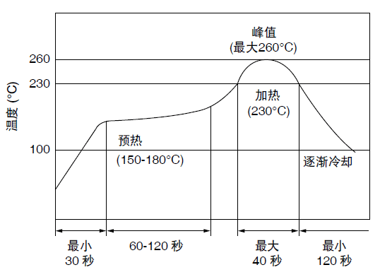
Table 1
| Specification |
Center Frequency |
455±2.0 KHz max |
Bandwidth(6dB) |
±17.5KHz min |
Selectivity(40dB) |
±40.0 KHz max |
Stop Band Attenuation(fo±100KHz) |
25dB min |
Ripple |
1.0dB max |
Insertion Loss |
5.0dB max |