Active Member
|
[China]

Address: No. 3111, Huaning Road, Shanghai, 201108, P. R. China
Contact name:Tan Ling

Shanghai Marine Diesel Engine Research Institute |
|
|
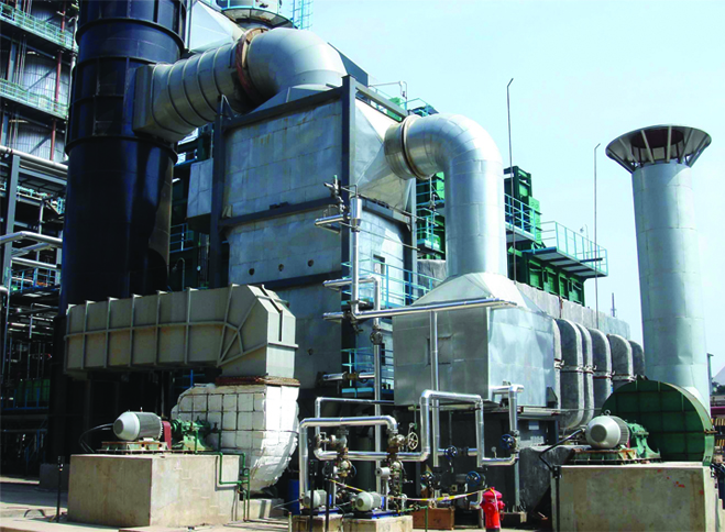
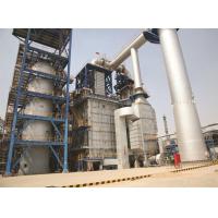
EPC Service Boiler Feed Water Preheter Consists Of Flue Gas Heat
Exchanger
Water-Heat-Medium technology
The water-heat-medium technology mainly functions to further recover the heat in low temperature
flue gas while make sure that no corrosion is caused at the
equipment so as to maximize the energy saving and minimize the
energy consumption.
Work Principle/Flow
* The water-heat-medium system mainly consists of flue gas heat exchanger, medium heat exchanger
(air preheater, feedwater preheater or other medium preheater), hot
water circulation pump, regulating valve set and etc. The flue gas
heat exchanger is located at the flue duct at the tail of heating
furnace or boiler and the medium heat exchanger is located at the
flow path of the medium to be heated.
* The water-heat-medium system uses a medium pressure deaerated water (2.5~5.0MPa) to maintain
the operating pressure of the system and improve the saturation
temperature of the heat medium water, which is helpful to improve
the heat transfer grade and maximize the waste heat recovery
process. During normal operation, water-heat-medium system itself
does not consume any deaerated water.
* The hot water circulation pump functions to overcome the flow
resistance of water-heat-medium system and continuously transfer
the heat absorbed by the heat medium water in the flue gas heat
exchanger to the medium to be heated. The bypass regulator valve is
to regulate the inlet temperature of heat medium water at the flue
gas heat exchanger inlet and make sure it is above the flue gas dew
point temperature.
Heat medium water flow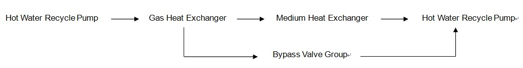
Process flow of water-heat-medium system
Structure & Parameter
| Service | Waste heat recovery |
| Equipment | Non-corrosion water-heat-medium preheater technology |
| Specification | Integral modularized structure |
| Components | Flue gas heat exchanger, medium heat exchanger (air preheater, feedwater preheater or other medium preheater), hot water circulation pump, regulator valve |
| Material | Shell: Q235B |
| Fabrication code | Steam boiler safety & technology supervision regulation |
| Flue gas flow | Min.: 5000Nm3/h |
| Inlet flue gas pressure | -5.0-10.0Kpa |
| Inlet flue gas temperature | 200-500℃ |
| Outlet flue gas pressure | -4.0-9.0Kpa |
| Outlet flue gas temperature | 120℃-150℃ |
| Refractory lining | Aluminum silicate fibre felt |
| External wall temperature of equipment | ≤60℃ |
| Utility | 2-Phase power supply: 10Kw |
| Main measuring points | Inlet flue gas temperature |
| Main interlocked alarm | nlet flue gas temperature high |
| Service life of critical equipment | Design service life: 8 years |
| Downtime of spare parts | 3~4 months |
| Warranty period | 12 months since normal operation or 18 months since delivery to site, whichever comes first |
| Scope of work/service | EPC |
| Response to service request | 24hs |
| Application | Oil refining, chemical and coal chemical industries |
Advantage
(1) Flexible and easy arrangement
(2) Wide adaptability to various fuels
(3) Accommodation of load change
(4) Improved operation safety
(5) Common use for multiple adjacent heaters
(6) Extended service life.
Typical Application
No. | Project | Specification | User | Qty. |
|---|---|---|---|---|
1 | 1# & 2# aromatic hydrocarbons hydrogenation cracking heater waste heat recovery system reconstruction | 1# Flue gas flow:11280kg/h | Sinopec Shanghai company | 2 sets |
2 | 1,200,000T/year catalytic plant waste heat recovery | Q179/505-10/79.2-3.82/348 | Shandong Dongming Petrochemical Group | 1 unit |
3 | 2,800,000T/year heavy oil catalytic CO waste heat recovery reconstruction | BQ211/800-42/135-3.82/450 | Sinopec Hainan company | 2 units |
4 | 1,800,000T/year catalytic plant waste heat boiler | BQC235/900-142-3.82/420 | CNPC Fushun company | 1 unit |
5 | 1,800,000T/year catalytic plant waste heat recovery reconstruction | Q310/540-230-3.82/380 | Yanchang Group Yulin Refining & Chemicals Co. Ltd. | 2 units |