

Active Member
|
[China]

Address: No. 12, Chuangxing Road, Baisha, Humen Town, Dongguan, Guangdong, China
Contact name:Calin Deng

GUANGDONG RUIHUI INTELLIGENT TECHNOLOGY CO., LTD. |
|
|
Unlike the other models commonly used in other feeder types, the NC
feeders are available in both pneumatic and mechanical versions.
The pneumatic NC feeder is a standard model because it is not limited to installation. It
can be used with a variety of presses, as well as hydraulic
presses, shears, and laser cutters.
However, there is a shortcoming that the relaxation action is
driven by the air source to drive the cylinder, and the speed is
slow, resulting in a limited overall feed speed.
The Ruihui mechanical NC feeder is optional, because its installation is limited, and it
is necessary to install a loose rod device on the processing
equipment, which can only be used with a punch press.
However, it has a significant advantage in that it is quick to
relax, suitable for high-speed feeding in short steps, and it is
extremely easy to relax and adjust when used with traditional
punching machines. Therefore, it is more suitable for mechanical NC feeders for high-speed stamping occasions and traditional punching
machines. .
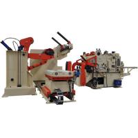
The NC feeder is composed of two parts: the mechanical head and the
electric control box. Although the mechanical control box is
identical to the pneumatic NC feeder, the head part is quite
different from the pneumatic NC feeder.
The mechanical NC feeder head can be divided into upper and lower
parts, a servo motor is fixed on the lower left side, and a spindle
is fixed on the right side of the motor. The spindle is driven by
the motor through the synchronous pulley.
A lower roller (active roller) and a gear are fixed on the main
shaft, and a handle is fixed on the lower right side. The left side
of the handle is connected with a rotating rod, and two irregular
adjusting blocks are fixed on the rotating rod.
In this way, it is necessary to adjust the distance between the
lower roller (active roller) and the upper roller (passive roller)
by simply rotating the handle to lift the adjustment block to the
upper portion, and the irregular adjustment block is for
diversifying the gear position for adjustment.
In order to facilitate the entry of the material to be processed,
the front end of the lower portion is sequentially fixed with a
bracket wheel and two adjusting wheels. The height of the two
adjusting wheels is preferably parallel to the center of the
distance between the main shaft and the counter shaft, so that the
feeding is facilitated.
The upper drum (passive roller) and the gear used in conjunction
with the lower drum (active roller) and the gear are fixed on the
upper portion, and are fixed by the secondary shaft, and a
relaxation wheel connected to the punching and relaxing rod is
fixed on the upper portion;
When the mechanical NC feeder feeds, the processing material passes
the lower roller and the upper roller, and the processing materials
are conveyed by clamping and driving of the two rollers; when the
punching slider pushes the bar to press down, the relaxation action
is realized, and the precise stepping is realized. Feeding action.
Specification:
| Model | MAC2-400 | MAC2-500 | MAC2-600 | MAC2-800 | ||
| Stock Width(mm) | 50-400 | 50-500 | 50-600 | 50-800 | ||
| Stock Thickness(mm) | 0.3~3.2 | 0.3-3.2 | 0.3-3.2 | -3.2 | ||
| Max.Coil Weight(kg) | 3000 | 3000 | 3000 | 5000 | 5000 | 7000 |
| Max.Coil O.D.(mm) | 1200 | 1200 | 1200 | |||
| Coil I.D.(mm) | 8 | 8 | 508 | 508 | ||
| Feed Length(mm) | ~500* | ~500* | ~500* | ~500* | ||
| Max. Line Speed(m/min) | 16-24 | 16-24 | 16-24 | 16-24 | ||
| Work Roll Number(pieces) | upper 6 lower 5 | upper 6 lower 5 | upper 6 lower 5 | upper 6 lower 5 | ||
| Feed Roll Number(set) | 1 | 1 | 1 | 1 | ||
| Main Motor(kw) | AC2.9 | AC2.9 | AC4.4 | AC4.4 | ||
| Mandrel Expansion | hydraulic | hydraulic | hydraulic | hydraulic | ||
| Reel Motor(kw) | 1.5 | 1.5 | 1.5 | 2.2 | 2.2 | 3.7 |
| Power(V) | 3 Phase 220V/380V/50HZ | |||||
| Operating Air(Mpa) | 0.49 | 0.49 | 0.49 | 0.49 | ||
Straigtening performance:
| tock Thicknees (mm) | Stock Width (mm) | |||
| 0.3 | 400 | 500 | 600 | 800 |
| 0.4 | ||||
| 0.6 | ||||
| 0.8 | ||||
| 1.0 | ||||
| 1.2 | ||||
| 1.4 | ||||
| 1.6 | 470 | 470 | ||
| 1.8 | 400 | 400 | ||
| 2.0 | 360 | 360 | ||
| 2.3 | 300 | 300 | 300 | 300 |
| 2.5 | 230 | 230 | 230 | 230 |
| 2.8 | 150 | 150 | 150 | 150 |
| 3.2 | 110 | 110 | 110 | 110 |
*1:(Pneumatic):Option in case of pneumatic mandrel expansion is
provi
![]()


