

Active Member
|
[China]

Address: Building 12, Songshan Lake, Small and Medium-Sized Science and Technology Park, Dongguan City, 523808, Guangdong Province, P.R.China
Contact name:KOMEG

KOMEG Technology Ind Co., Limited |
|
|
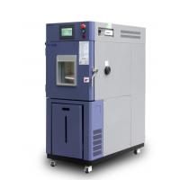
Intelligent Auto Parts Lab Temperature Humidity Chamber High Precision Test For Electronics
| Ⅰ.Product Overview | |||||||||||||||||||||||||||||||||||||||||||||
Able to accurately simulate a wide range of complicated natural environments, and is suitable for reliability test in industrial products. Meet GB5170.2.3.5.6-95 standard requirements of environmental testing equipment and test methods for the basic parameters of electric and electronic products under the condition of humidity, low temperature, high temperature, and constant heat. | |||||||||||||||||||||||||||||||||||||||||||||
| Ⅱ.Application | |||||||||||||||||||||||||||||||||||||||||||||
Applicable to environmental adaptability and reliability test in such industrial units as electronics, electrical appliance, battery, plastics, food, paper product, vehicle, metal, chemistry, building material, research institution, inspection and quarantine bureau, university etc.. | |||||||||||||||||||||||||||||||||||||||||||||
| Ⅲ.Features | |||||||||||||||||||||||||||||||||||||||||||||
● GB-2423.1-89(IEC68-2-1)Test A:Low Temperature Test ● GB-2423.2-89(IEC68-2-2)Test B:High Temperature Test ● GJB360.8-87(MIL-STD.202F) High Temperature Life Test ● GJBl50.3(MIL-STD-810D) High Temperature Test ● GJBl50.4(MIL-STD-810D) Low Temperature Test ● GB2423.3-93(IEC68-2-3)Test Ca:Constant Heat Test ● GB2423.4-93(IEC68-2—30)Test Db:Damp Heat Alternative Test ● GJBl50.9-93(MIL-STD-810D) Damp Heat Test | |||||||||||||||||||||||||||||||||||||||||||||
| 1.Energy conservation | Bypass mode to adjust cooling capacity to achieve a constant temperature and humidity effectively | ||||||||||||||||||||||||||||||||||||||||||||
| 2.Easy Operation | ※Using company owned brand KOMEG KM-3166 LCD touch screen controller with PID control parameters setting ※Flexible approach for data collection and recording | ||||||||||||||||||||||||||||||||||||||||||||
| 3.High reliability | ※Key parts are imported, ensuring the service life and high reliability ※Efficient oil separator to ensure the service life of the compressor | ||||||||||||||||||||||||||||||||||||||||||||
| Ⅳ.Main Technical Parameters | |||||||||||||||||||||||||||||||||||||||||||||
| 1. Chamber | |||||||||||||||||||||||||||||||||||||||||||||
| 1.1 Workspace volume | optional | ||||||||||||||||||||||||||||||||||||||||||||
| 1.2 Exterior size | optional | ||||||||||||||||||||||||||||||||||||||||||||
| 2. Temperature | |||||||||||||||||||||||||||||||||||||||||||||
| 2.3 Temperature range | -20 ~ 150 ℃ | ||||||||||||||||||||||||||||||||||||||||||||
| 2.4 Temp Deviation | ±2.0℃ | ||||||||||||||||||||||||||||||||||||||||||||
| 2.5 Temp Constancy | ±0.5℃ | ||||||||||||||||||||||||||||||||||||||||||||
| 2.6 Temp Uniformity | ±2.0℃ | ||||||||||||||||||||||||||||||||||||||||||||
| 3. Humidity | |||||||||||||||||||||||||||||||||||||||||||||
| 3.1 Humidity range | 20%R.H.~98%R.H | ||||||||||||||||||||||||||||||||||||||||||||
| 3.2 Control range | |||||||||||||||||||||||||||||||||||||||||||||
| 3.3 Humidity deviation | ±3.0%RH(>75%RH) ±5.0%RH(≤75%RH) | ||||||||||||||||||||||||||||||||||||||||||||
| 3.4 Humidity uniformity | 3.0%RH(no-load) | ||||||||||||||||||||||||||||||||||||||||||||
| 3.5 Humidity constancy | ±2.0%RH | ||||||||||||||||||||||||||||||||||||||||||||
| Ⅴ.Chamber Structure | |||||||||||||||||||||||||||||||||||||||||||||
Overall structure and chamber was composed of three parts as below. Insulation box, separate refrigeration units, and electrical control cabinet. | |||||||||||||||||||||||||||||||||||||||||||||
| 1.Insulation box | ※ wall material: high-quality carbon steel with static color spray ※ inner wall material: SUS304 # matte stainless steel plate ※ Insulation materials: rigid polyurethane foam insulation layer + glass fiber. | ||||||||||||||||||||||||||||||||||||||||||||
| 2.Door | Heating wire was installed at the door frames to prevent condensation at low temperatures. | ||||||||||||||||||||||||||||||||||||||||||||
| 3.Observation window | With observation window, multi-hollow electric insulation coated glass prevent condensation effectively | ||||||||||||||||||||||||||||||||||||||||||||
| 4.Cable port | Φ50mm*2 located on both sides(each*1) with rubber stopper and plastic cover | ||||||||||||||||||||||||||||||||||||||||||||
| 5.Lighting device | 11W/AC220V *1 located on observation window | ||||||||||||||||||||||||||||||||||||||||||||
| 6.Water outlet hole | Available for drain the condensate water | ||||||||||||||||||||||||||||||||||||||||||||
| 7.Sample holder | Two layers of stainless steel sample holder. | ||||||||||||||||||||||||||||||||||||||||||||
| 8.Mobile Casters | Mobile Casters *4 with foot cups | ||||||||||||||||||||||||||||||||||||||||||||
| 9.Electric control box | Total power circuit breaker, over-temperature protection. | ||||||||||||||||||||||||||||||||||||||||||||
| 10. Water supply system | Water pump automatic supply | ||||||||||||||||||||||||||||||||||||||||||||
| Ⅵ.Air-conditioning system | |||||||||||||||||||||||||||||||||||||||||||||
| 1. Control mode | Forced ventilation loops design, balance temperature & humidity control system (BTHC). | ||||||||||||||||||||||||||||||||||||||||||||
| 2. Air conditioning device | Top-mounted diffuser to ensure uniformity of temperature and humidity Long axis centrifugal fan, evaporators, heaters, humidifiers was installed on air conditioning box | ||||||||||||||||||||||||||||||||||||||||||||
| 3. Heating | Quality nickel-chromium alloy wire electric heaters, Non-contact control mode (SRR). | ||||||||||||||||||||||||||||||||||||||||||||
| 4. Cooling | Sine wave pattern aluminum finned copper tube air heat exchanger (air-cooled) | ||||||||||||||||||||||||||||||||||||||||||||
| 5. Water supply | Inner water supply mode | ||||||||||||||||||||||||||||||||||||||||||||
| 6. Humidifier | Basin heated humidification Stainless steel sheathed heater Heater control: non-contact period, such as pulse width modulation, SSR (solid state relay) Water level control devices, anti-dry unit heater | ||||||||||||||||||||||||||||||||||||||||||||
| 7. Compressor | Tecumseh brand Compressor | ||||||||||||||||||||||||||||||||||||||||||||
| 8. Throttling device | Thermal expansion valve & Capillary
| ||||||||||||||||||||||||||||||||||||||||||||
| 9. Refrigerant | R404a Environmental friendly high temperature level of refrigerant | ||||||||||||||||||||||||||||||||||||||||||||
10. Parts and its Brand
|
| ||||||||||||||||||||||||||||||||||||||||||||
| 11. Refrigeration Technology | ※ Nitrogen welding, two-stage rotary vane vacuum pump, ensure that the internal cooling system clean and reliable. ※water tray located at the bottom of the compressor to ensure condensate water drain through pipe freely at the rear of the chamber. | ||||||||||||||||||||||||||||||||||||||||||||
| Ⅶ,Control System | |||||||||||||||||||||||||||||||||||||||||||||
| 1. Curve recording function | Pt100 | ||||||||||||||||||||||||||||||||||||||||||||
| 2. Controller | KOMEG brand KM-3166 LCD Touch screen controller with PID control parameters setting
| ||||||||||||||||||||||||||||||||||||||||||||
| 3. Display | Temperature and humidity settings (SV) Actual (PV) value can be displayed directly, Execution of the program can display numbers, Paragraphs, remaining time and cycles, running time display, Program editing and graphic curve display, Fixed or program operation status display, 7-inch TFT display screen. | ||||||||||||||||||||||||||||||||||||||||||||
| 4. Resolution | Temperature: + 0.01 ℃; Humidity: + 0.1%; Time: 1min | ||||||||||||||||||||||||||||||||||||||||||||
| 5. Setting range | Temperature can be adjusted based on the working temp of the equipment (the upper limit +5 ℃, the lower limit -5 ℃) | ||||||||||||||||||||||||||||||||||||||||||||
| 6. Running mode | programmable running ,constant running and booking boot | ||||||||||||||||||||||||||||||||||||||||||||
| 7. Setting mode | Touch mode input | ||||||||||||||||||||||||||||||||||||||||||||
| 8.Communication interface | Data collection when connected to a computer Can be used as monitoring and remote control system, Multiple machines synchronization control available. | ||||||||||||||||||||||||||||||||||||||||||||
| 9. U disk Memory card | 1G-8G available | ||||||||||||||||||||||||||||||||||||||||||||
| 10. Data collection | RAM with battery protection settings, data can be saved, maximum historical data memory storage is 90 days (when the sampling time is 1min) | ||||||||||||||||||||||||||||||||||||||||||||
| 11.Power off memory | Power recovery mode can be set as hot start, cold start and stop. | ||||||||||||||||||||||||||||||||||||||||||||
| 12. Pre-set function | boot time can be set freely and machine runs automatically when turning on power | ||||||||||||||||||||||||||||||||||||||||||||
| 13.Software environment | Windows2000 or Windows XP | ||||||||||||||||||||||||||||||||||||||||||||
| 14. Network Connection | Can be connected to Ethernet, remote control function, data collection, can simultaneously control multiple machines. | ||||||||||||||||||||||||||||||||||||||||||||
| 15. Function | Fault alarm and causes handling prompts, power protection, the lower limit temperature protection, timer function (automatic start and automatic stop running), self-diagnostic function. | ||||||||||||||||||||||||||||||||||||||||||||
| Ⅷ. Electrical control system | |||||||||||||||||||||||||||||||||||||||||||||
1. Power distribution Control cabinet | ※ Cooling fan ※ Switchboard ※ Specimens terminal ※ RS-485 physical interface (if purchase centralized monitoring software ) ※ The total power leakage circuit breaker. | ||||||||||||||||||||||||||||||||||||||||||||
2. Parts and its Brand
|
Note: Two options listed is for alternate choice and backup purpose | ||||||||||||||||||||||||||||||||||||||||||||
| 3. Protection System | 3.1 Cooling System: ※ Compressor overpressure protection ※ Compressor motor overheating protection ※ Compressor motor over current protection ※ Condenser fan overheating protection
3.2 Laboratory ※ Adjustable over-temperature protection --- over temperature protection mode 1 ※ Test space temperature fuse --- over temperature protection mode 2 ※ Air conditioning channel limit over temperature --- over temperature protection mode 3 ※ Controller set over temperature shutdown alarm --- over temperature protection mode 4 ※ Fan motor overheating.
3.3 Other ※ The total power phase sequence and phase loss protection; ※ leakage protection; ※ Load short-circuit protection. | ||||||||||||||||||||||||||||||||||||||||||||
| 4. Alarm | Equipment stops running and sends audible alarm when the above protection appears, meanwhile, fault, causes and solutions will be displayed on the screen. | ||||||||||||||||||||||||||||||||||||||||||||
| Ⅸ. Installation | |||||||||||||||||||||||||||||||||||||||||||||
1. Power
| ※AC380V±10%, 50Hz±1Hz,3 phase 4 wires +Ground Wires ※Power cable is connected to the air switch in control box ※Total Power ~8 kW, 10A; ※Voltage permitted:AC(1±10%)380V ※Frequency permitted:(1±1%)50Hz ※Resistance of ground wire less than 4Ω TN-S mode or TT mode for power supply ※Must be equipped with an independent and private air or power switch
| ||||||||||||||||||||||||||||||||||||||||||||
| 2. Water Supply | ※Humidification water: water or deionizer water Maximum consumption: 7L / h ※ When using RO systems, water supply requirements are Water pressure 0.2MPa, pipe line DN10 Maximum Consumption: 7L / h. water flow | ||||||||||||||||||||||||||||||||||||||||||||
| 3.Surrounding environment | 5 ~ 35℃,Humidity≤85%R.H | ||||||||||||||||||||||||||||||||||||||||||||
| 4. Air quality | No high concentrations of dust or corrosive gases | ||||||||||||||||||||||||||||||||||||||||||||
| 5.Installation environment | ※distance from the wall to both sides and rear of chamber more than 800mm, to the front more than 1500mm. Provide independent power distribution switchgear and humidification condensate drains, and external power connector device is necessary ※ground level, well-ventilated, non- flammable, explosive, corrosive gases and dust ※No strong electromagnetic radiation nearby ※With floor drain ( less than 2 meters from the refrigeration unit ) ※venue floor load capacity : not less than800kg/m2 ※leave adequate space for maintenance | ||||||||||||||||||||||||||||||||||||||||||||
| 6. Ground wire | Grounding resistance less than 4Ω, grounding bolts located at the base of the cabinet. | ||||||||||||||||||||||||||||||||||||||||||||
| 7. Drainage | Drain hole installed at the base of the housing | ||||||||||||||||||||||||||||||||||||||||||||
| 8. Cable port | φ50, φ80, φ100, φ120mm cable port, location and number can be customized according to user requirements if chamber body structure allows. | ||||||||||||||||||||||||||||||||||||||||||||
| 9. Equipment storage | ※When the device does not work, the ambient temperature should be maintained within 0 ~ 45 ℃ ※When the ambient temperature is below 0 ℃, the water remaining in the device should be drained to avoid water pipes freezing and broken | ||||||||||||||||||||||||||||||||||||||||||||
| 10.Centralized monitoring | For remote centralized monitoring, need another PC (Windows 2000/XP operating systems, a COM port and a USB port); Equipped with RS-485/RS-232 converter and a communication cable 25m. | ||||||||||||||||||||||||||||||||||||||||||||
| Ⅹ.Technical Documentation | |||||||||||||||||||||||||||||||||||||||||||||
| 1.Technical Documentation | ※Operation Manual*1 | ||||||||||||||||||||||||||||||||||||||||||||


