
|
|
[China]

Trade Verify
Address: No.A1507H2 Xinhe Century Building, 3069 Caitian Rd, Gangxia Community, Futian District, Shenzhen City, China
Contact name:Ricky Zou

RULETEAM CONNECTION TECHNOLOGY (SHENZHEN) CO.,LTD |
|
Verified Suppliers
|
|
|
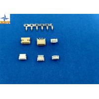
1.25mm Pitch Circuit Board Wire Connectors With Lock Structure PA66 / LCP Material
1, The specification of the product including basic size information, electrical and mechanical properties.
| Basic size information | |||
| Suitable terminals | A1500T series | ||
| Suitable wafer | A1500WR/WV series | ||
| Pitch | 1.50mm | ||
| Color | white | ||
| Row | single | ||
| Lock to mating part | without | ||
| Circuits | 2 to 14 | ||
| Wire insulation diameter | 1.15mm Max. | ||
| Terminal materials | phosphor bronze, tin-plated | ||
| Electrical properties | |||
| Current Rating | 1A AC, DC | ||
| Voltage Rating | 125V AC, DC | ||
| Contact Resistance | 20mΩ Max | ||
| Insulation Resistance | 100mΩ min | ||
| Withstanding Voltage | 500V AC/minute | ||
| Mechanical properties | |||
| Temperature range | -25℃ to 85 ℃ | ||
| Other information please kindly check the following picture. | |||
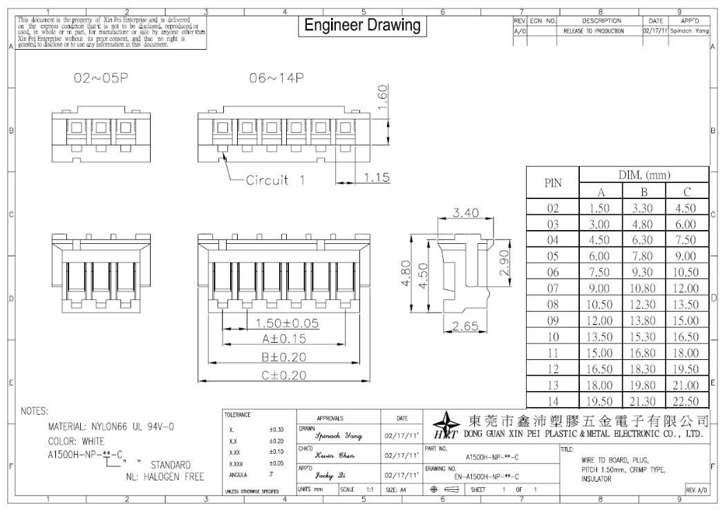
2, Related drawing and report
Folllowing pictures are out testing report and exact engineering drawing for your information, please kindly check it, wish it can help you to get what you really need.

Revision Control
Product Summary Test Report Origination
|
This document is the property of Xin Pei Enterprise and delivered on the express condition that it is not be disclosed, reproduced or used, in whole or in part, for manufacture or sale by anyone other than Xin Pei Enterprise. Without its prior consent, and that no right is granted to disclose or to use any information in this document. | ||||||||||||||||||||||||||||||||||||||||||||||||||||||||||||||||||||||||||||||||||||||||||
1. Scope This specification covers the requirements for product performance of 1.50mm pitch wire to board connectors series.
2. Construction,Dimensions,Material & Plating See the attached drawings
3. Ratings & Applicable Wires
*: Including terminal temperature rise
4. Electrical Performance
5. Mechanical Performance
| ||||||||||||||||||||||||||||||||||||||||||||||||||||||||||||||||||||||||||||||||||||||||||
6. Environmental Performance And Others
7. Actuator Insertion/Withdrawal Force [Unit : kgf]
| ||||||||||||||||||||||||||||||||||||||||||||||||||||||||||||||||||||||||||||||||||||||||||
3, HRT main product show
You can get more series parts from the below picture, it's our main product picture from our different type.


